This drawings shown here are to provide general information about the overall design of the Muon Tracker. These drawings are not to be used for construction or to address detailed design issues. The drawings which are to be used for those purposes are controlled drawings in the possession of the PHENIX System Engineering and Integration Group.
[Note: The figure numbers are anchors for the same drawing in PDF format, which is more useful for printing.]
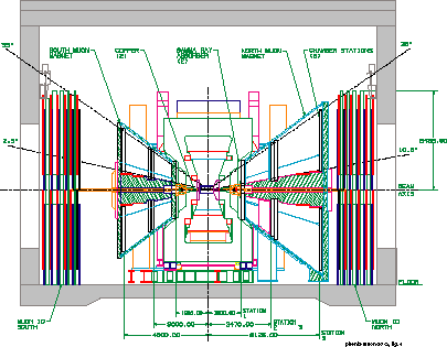
Figure 1: North and South Muon Arms of PHENIX including the Muon Tracking chambers in the North and South Muon Magnets, respectively.
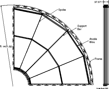
Figure 2: A quadrant of the Station 1 chambers. The sizes of these chambers are the same for both the North and South Muon Arms.
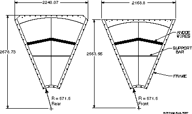
Figure 3: The two different sized chambers which are used for the North Muon Arm Station 2. The smaller chamber is located closer to the interaction point than the larger chamber. Two different chamber sizes in each arm are required to allow neighboring octants to overlap their frames and thus help to minimize acceptance losses due to the frames. The dimensions shown in the figure are for the North Muon Arm.
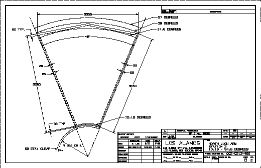
Figure 4: An octant of the Station 3 chambers. The dimensions shown in this drawing are for chambers to be mounted in the North Muon Magnet. The chambers for the South Muon Magnet are smaller.
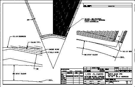
Figure 5: The details at the inner radius of the Station 3 chambers for the North Arm are shown.