Station 0
- Slowly walk the disk to the cage.
- The first thing to arrive at the cage is the long thermocouple wire,
on the
right side. Feed it forward through the hole in he cage.
- Next comes the other thermocouple wire, and the hoses. Careful with the
hoses!
- Move the disk in place and
- Push in the three alignment pins - sides first,
bottom last.
- At this stage, you could cut the strings that hold the extension cables
to the hoop, and remove the lifting fixture + hoop. Alternatively, if the
alignment is good, you could first plug in the extension cables, before
cutting te strings and removing the lifting fixture.
- Plug in the extension cables. The big wheel is a bit floppy, so you
have to reach around and support the disk from behind when you plug them in
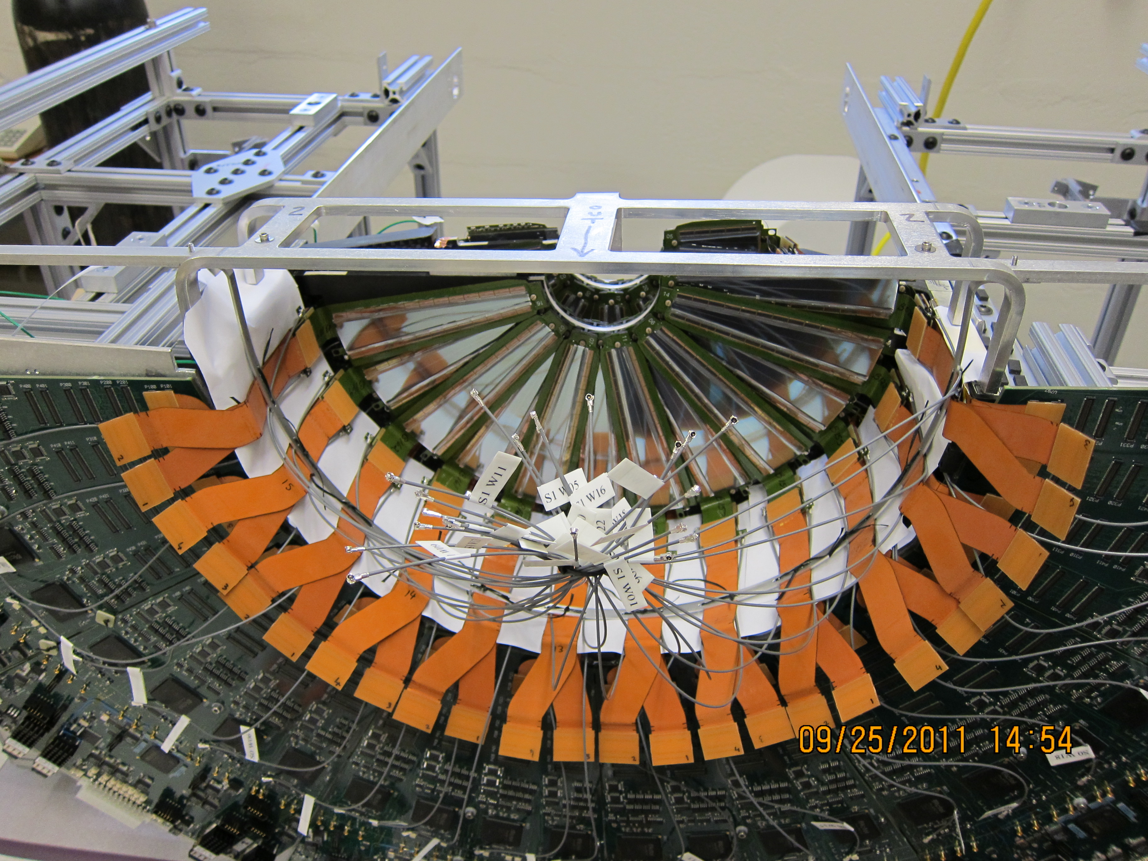
- Untie the bias cable bundles. Currently, the cables that go from the bias
distribution boards to the ROC are not yet available, so for testing, bias
voltage is delivered to the wedges by connecting a temporary cable directly
to the bias cables.
| 
|
Using kapton tape, tape down the extension cables and bias wires.
- On the ROC end, make sure the cables are flat against the ROC board.
When checking this, make sure the cooling plate is in the right location (the
center plane of the cooling plate should be even with the corner of the cage).
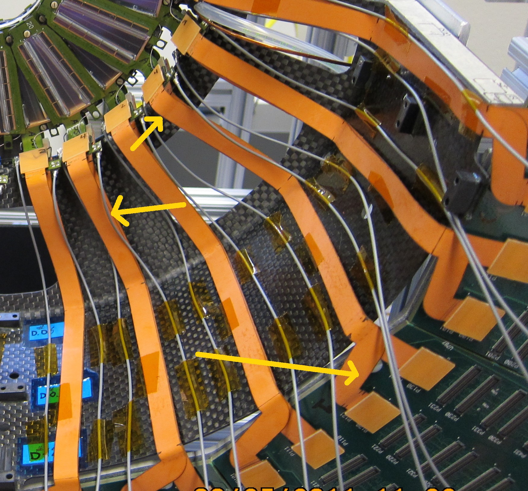
- On the HDI end, the even-numbered cables stick out the most.
Taping them to their odd-numbered partner lowers the profile.
- Bias cables want to curve out. If you swivel them by 90° so
that they start parallel to the disk, they can be routed so they don't
stick out
|
| Find the spare large disk and mount it in the Station-1 location
using three alignment pins.
| 
|
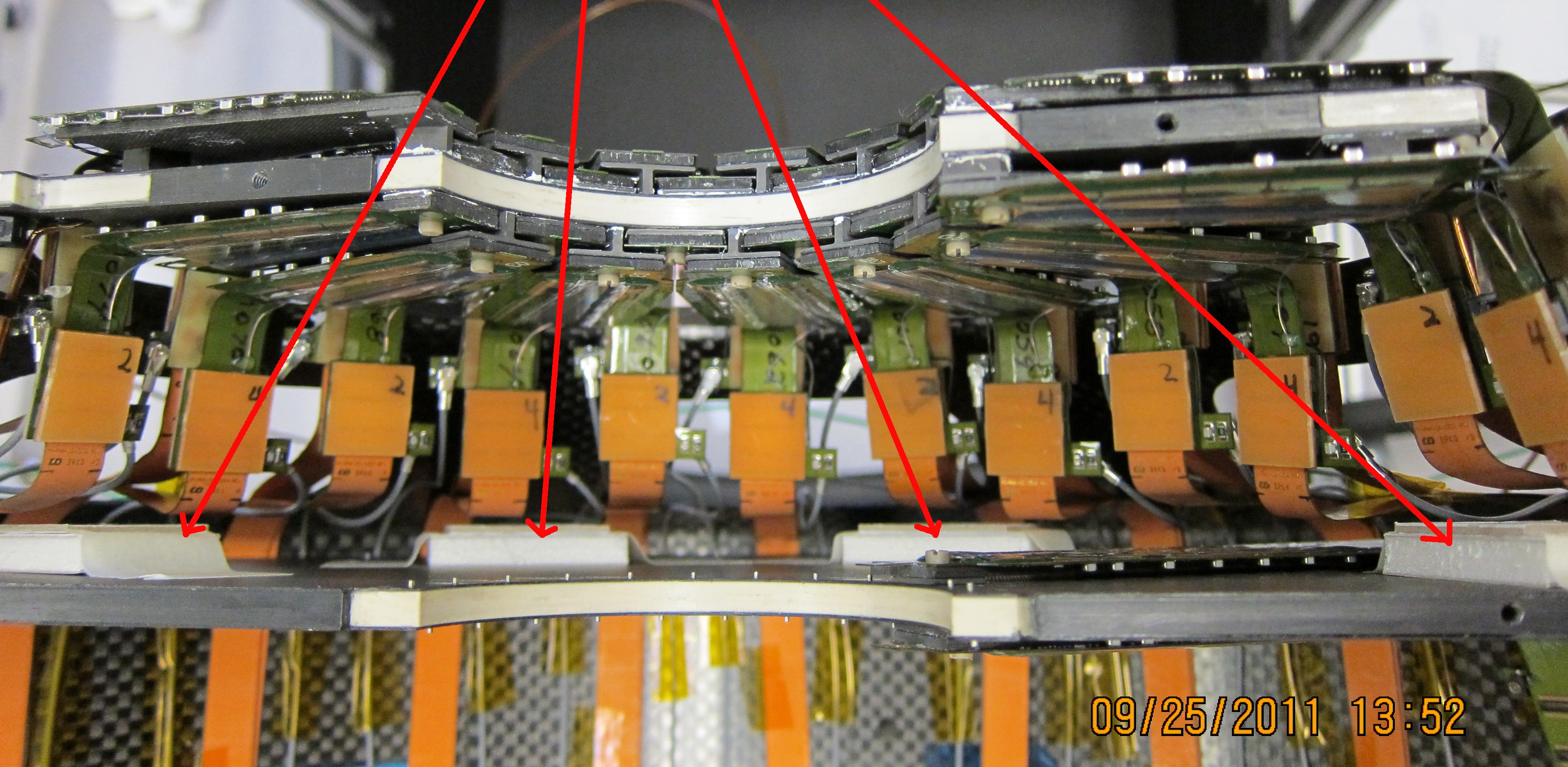
On the back of this disk are taped little blocks, and the top surface
of these blocks is where the Silicon surface would be of the tall Station-1
wedges.
- Look down into the space between Stations 0 and 1, see if
any of the extension cables or bias wires would touch the Station-1
silicon
- Take out the spare disk, and tape the offending cables out of the way,
- Check again with the spare disk.
|
- Put labels on the St.0 thermocouple wires and cooling hoses (use 'bottom' and 'top', see the writing on the assembly frame)
- Ground the St.0 carbon support disk
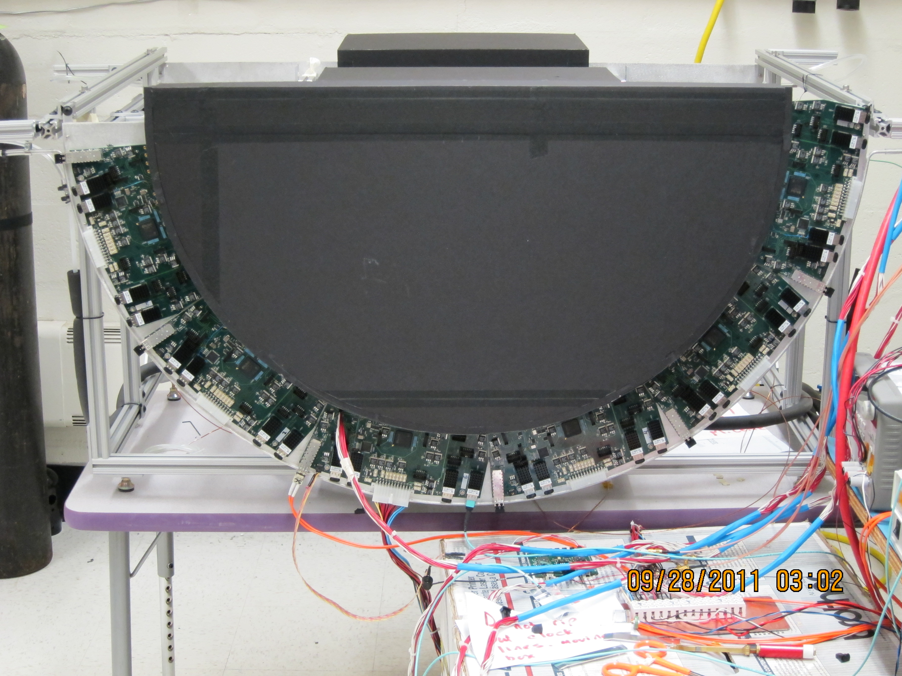
- Put the bottom and top dark boxes back in place
- Test all wedges!
While testing, you need to run the chiller in order to keep the ROCs cool.
In the IR, the chiller runs at 0°C. In the lab, we found that there was
a lot of condensation dripping from the disk, So
- Set the chiller to 10°C (50°F)
- Don't run the chiller continuously
| 
|
Station 1
- Line the cage + Station-0 cables with paper strips. This prevents the
Station-1 cables from snagging on the '0 cables as you move in.
- The Station-1 cooling tubes and TC wires also feed forward through the
same holes in the cage as the Station-0 hoses.
- The hoses have 2 cable ties on them near the hose barb. The thickness
of the hose and cable ties is such that the cable tie is wider than the
mounting tab on the disk. This means the disk can not approach its final
position along the z-direction.
Because the hoses feed through the cage opening, you can also no approach
from a vertical direction. You have to come in from a '45°' angle,
with the disk tipped at an ~30° angle so that the bottom is closer to you.
This way you can move the disk so that the cable
tie goes up and over the cage mount point.
- When the top mount points are in place, put in the alignment pins.
- Now you can push back on the bottom mount tab until it lines up with the
cage mount point, and put in the 3rd alignment pin.
- The wide cables are stiffer, so you can cut the strings, remove the
two screws on the disk edge and remove the lifting fixture and hoop.
- Pull on the paper liners and slip them out on either side.
- Plug in all cables, tape them down, label the TC wires and hoses,
put the dark covers back and test all wedges.
| 
|
Station 2
Station 2 proceeds much like station 1:
- Line the cage+ cables with 2 paper strips, one for each side, to
prevent snags.
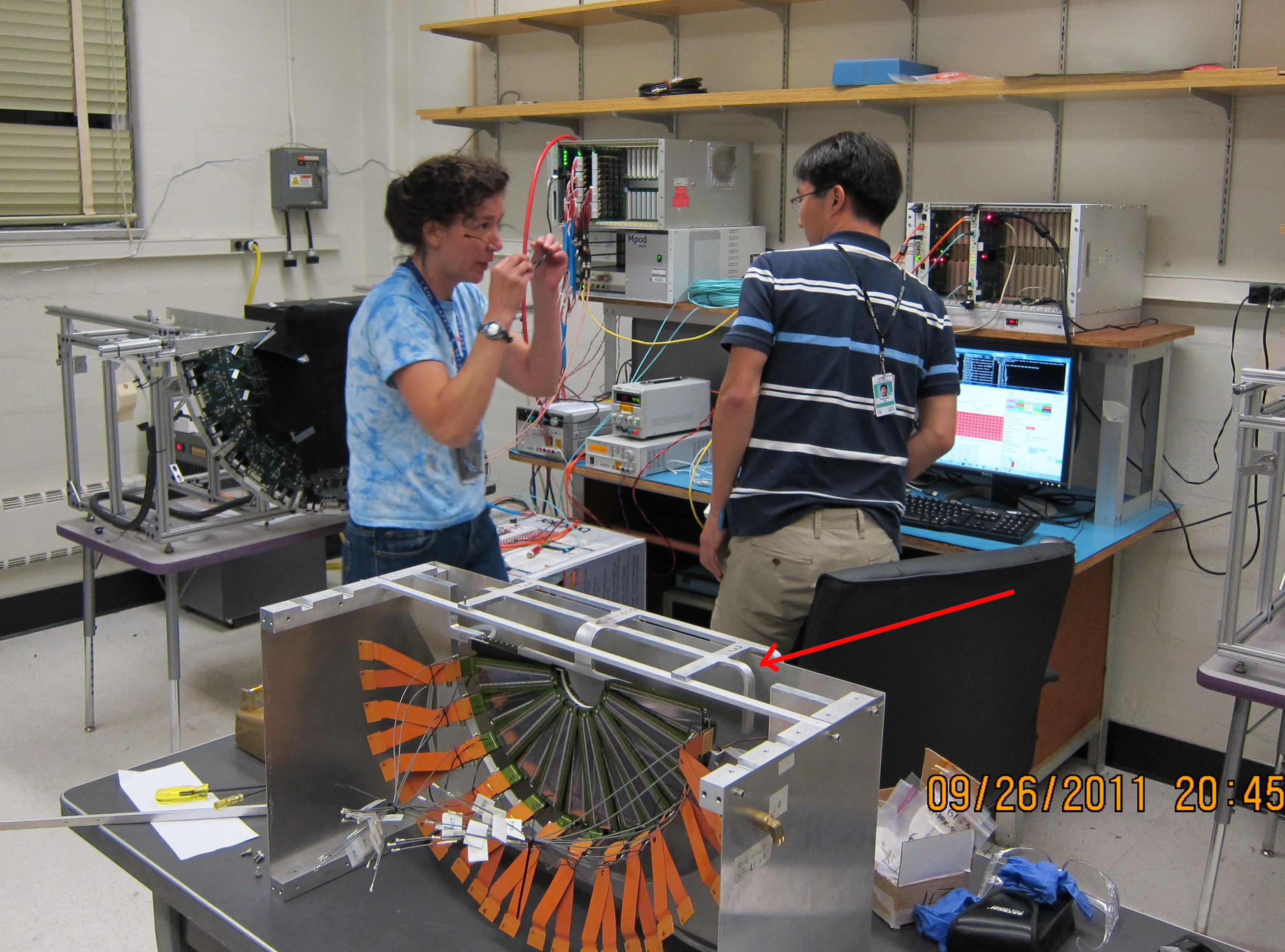
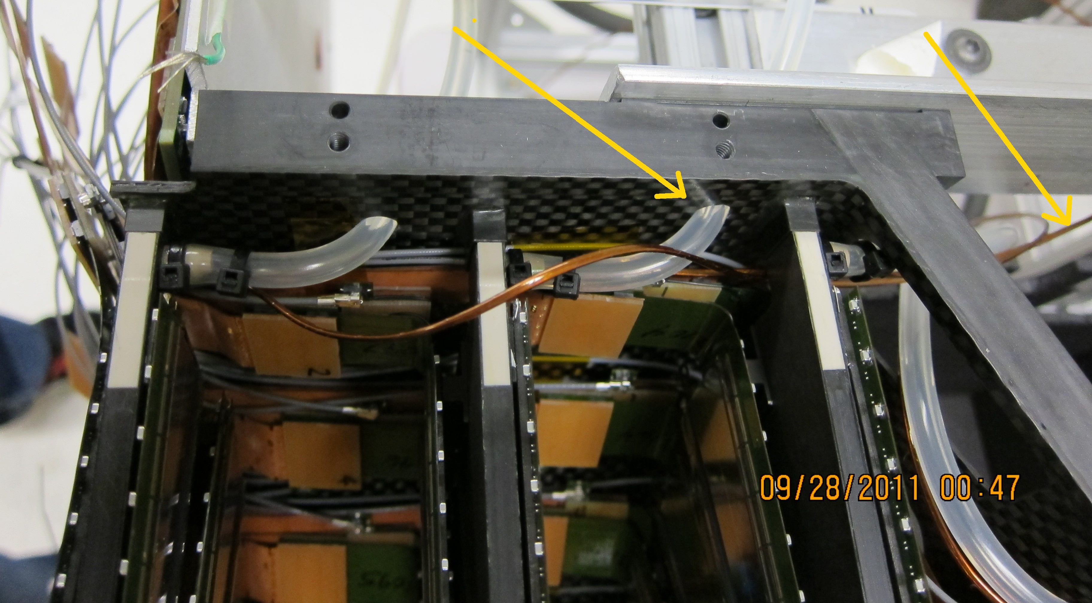
- The hoses get fed out through the holes in the side of the
cage, indicated by the arrow. The thermocouple however goes forward
together with the other TC wires.
- Again you have to go up-and-over for the cable ties to clear the cage
mount points
- Station 2 cables are short and stubby so there is no hoop + strings.
| 
|
Station 3
Station 3 proceeds much as the others, but:
- No paper liner is needed
- Note the clamp on the top left. This pulls the cooling plate back to
the stop on the assembly frame, so that you can access the alignment pin
and screw holes of this disk.
- Again the hose goes through the (far) hole in the side, and the
TC wire goes forward with the other wires.
| 
|
When all four stations are in and tested:
- Check for ROC buttons
- Route eand tape down bias cables, if needed
- Check that you have grounding wires from each of the disks, and from
the cage, fed out from the perimeter of the ROC boards, and that they
have labels
- Add the red foam thermal strip to the ROC surface
- Put the cover on, or get the FR4 end
plate and mount it with 12 screws on the extender posts on the ROC board
center lines.
- Connect a gas line so that the cage gets flooded with dry Nitrogen
|
Final checks (Walt's email 20 October):
- group wedge bias cables together as they route across the ROC
boards, they come out as groups between the wedge cables
- verify all routing and labeling of thermocouples and cooling lines
from station disks
- add 72. inch thermocouples to Big-Wheels and label, route along
outside of Big-wheel
- verify installation of cage grounds and disk grounds
- verify that all screws and proper length pins (station disks) are
installed in cage assembly
- gas seal strips need to be installed between ROC cards on
Big-wheel, this is currently cut out of 1/4 inch thick red-silicone foam
- a 1/2 inch thick strip of red-silicone rubber is installed on the
surface of the ROC boards along the radial seal location on these cards
- look at the possibility of adding .625 + .020 inch spacers at the
inner radius of the ROC cards and the gas enclosure end plates -
between the two
- install gas enclosure end plates, black side towards detector,
flat head screws, the 1/2 inch red seal on the ROC cards mates with the
1/4 inch seal on the gas enclosure end plate
- prep FVTX carrier for transport tot Chemistry
| | | |