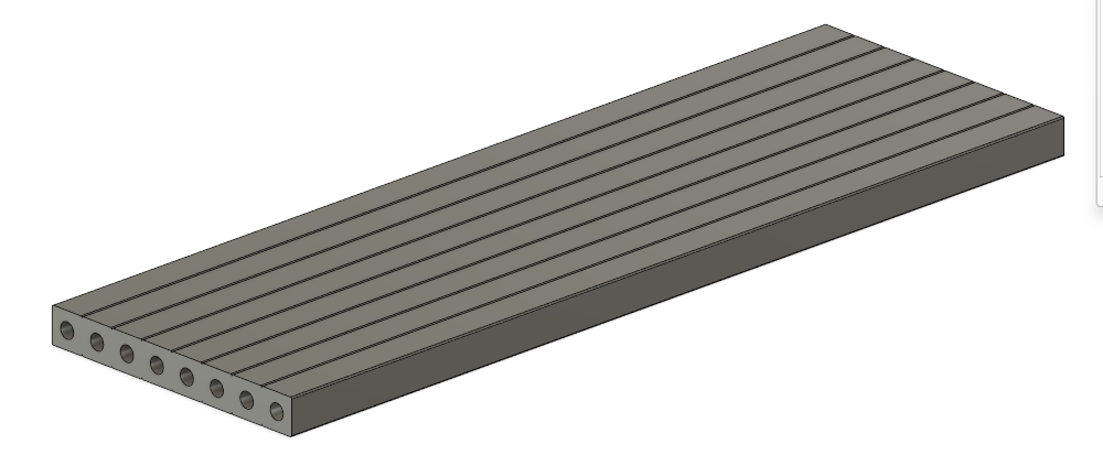
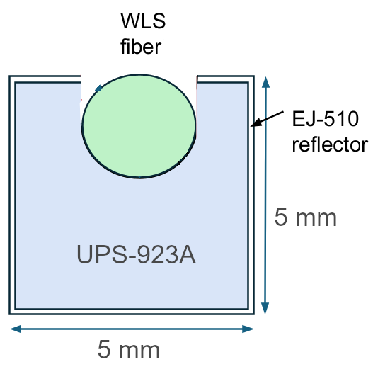
2mm wavelength-shifting fibers
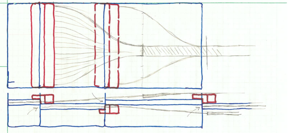
| Light generated in our plastic wavelenght shifting fibers propagates
mostly along the fiber axis. Therefore if we couple the 2mm wls fibers
to our clear 0.5mm readout fibers, the effective light yield at the
detectors increases a lot over using 1mm wls fibers. Also, we will
switch to 5×5mm square scintillating plastic bars.
Since we don't have the bars yet, print some stand-ins so we can
explore the new mechanical arrangements.
| 
| ||||||||||||
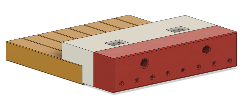
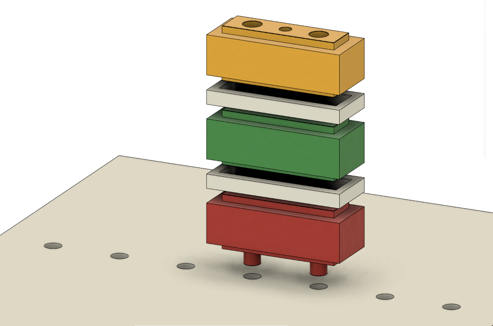
| Next is the 50 cm long prototype tray to hold one block wide
(#1 shown, 8 fibers)
wide. The bottom
has 8 grooves, 4mm wide, to hold outgoing wls fibers from block #1
and block #3. Fibers from #2 and #4 will go over the top, and #5 and 6
come
straight out.
Note this unit is 2.5 mm thicker than the same unit with 1mm fibers. | 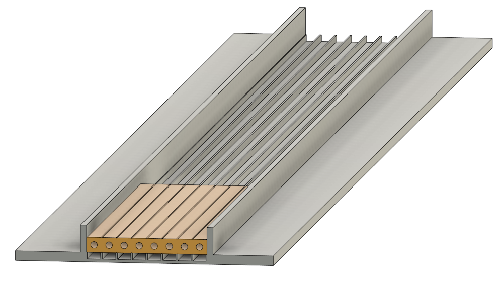
| ||||||||||||
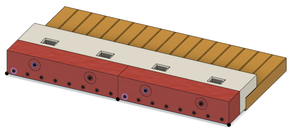
| The original design for the full-length units has 7 or 8 blocks. | 
| ||||||||||||
| With more than 6 blocks, fibers from 1,3,5 are routed under, and
2,4,6 are routed over the blocks.
3 fibers side-by-side take up 6mm, and each scintillator is only 5mm wide, so the outgoing fibers need to be stacked 2 deep. Therefore each tray is now 2.5+2+2=6.5mm thicker than before. | 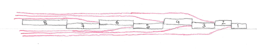
| ||||||||||||
| The new stackup measures 22 mm, which makes it just barely possible to place the two layer pairs 5 cm apart. | 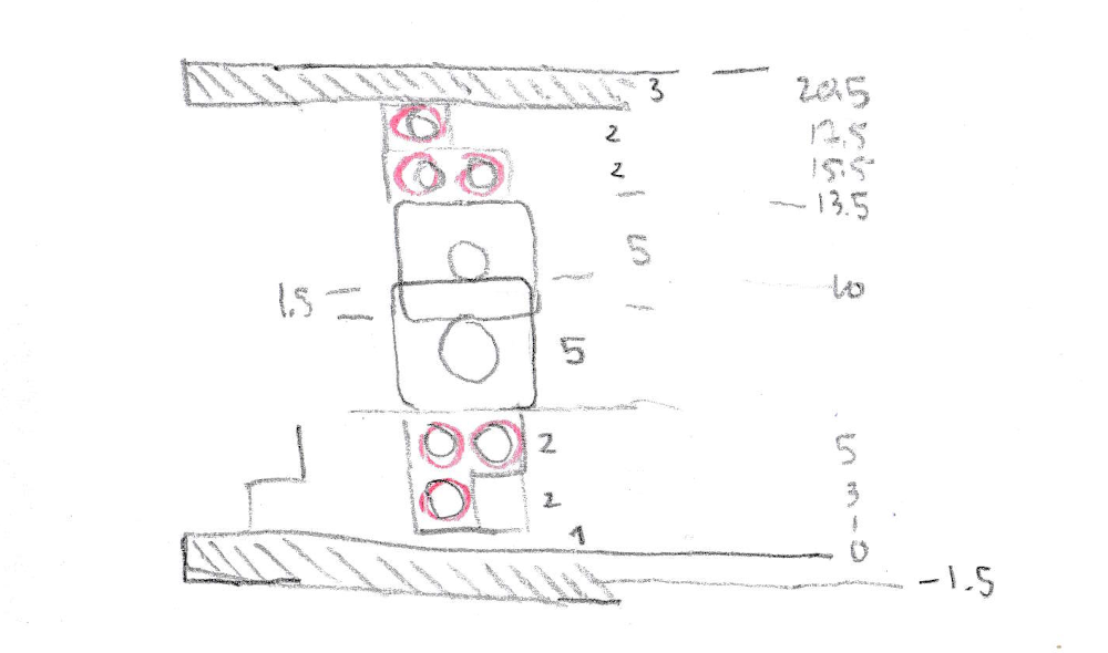
| ||||||||||||
| Not clear if the new connectors can be made to fit inside of 25 mm, since their bending radius is 2x bigger. | | ||||||||||||
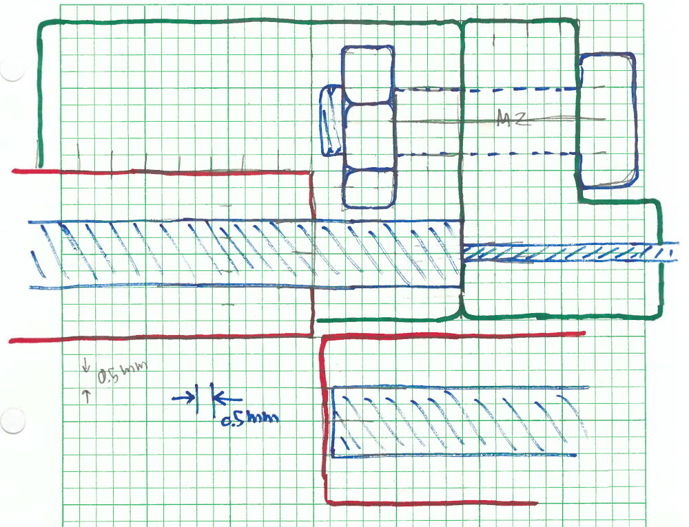
| Plan B: What if we couple the clear fibers directly to the scintillator blocks? Here is a possibility.
RED: 5mm scintillator bars
BLUE: 2mm wls fiber, 0.5 mm clear fiber
GREEN: left block is glued to the scintillator
block, right block holds the clear fiber
and is screwed on with M2 screws.
This stack would be 2× 9.5 mm = 19 mm thick, plus 1.5mm for the
bottom tray, 3.0/2 for the support panel, 0.5 mm for fibers going
over the top, total 22.5 mm (less than 25).
|

back