Readout plate
|
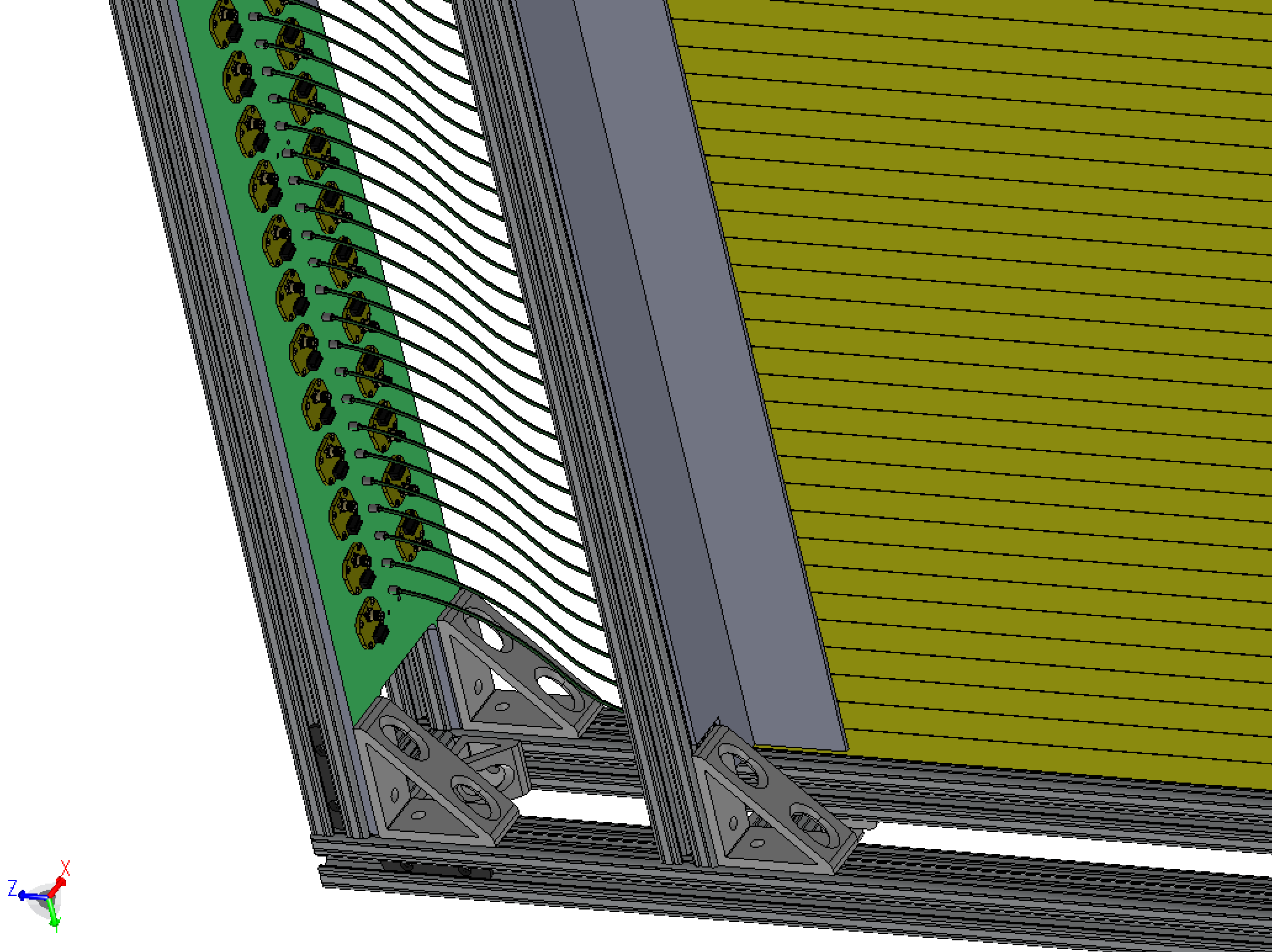
Based on this sketch
Snapshots from this EASM file | |
| Fibers go from the end of the 1m bars to a small insert in a readout plane (colored green, nominally 1/4" Al). The vertical offset of the fibers is 3", lifting the preamps away from the hot midplane, and clearing a space below the plate for cable bundles to exit. The preamp boards sit on this side of the plate, as shown, mounted at a small angle so that ribbons and coaxes don't get ito each others' way. |
|
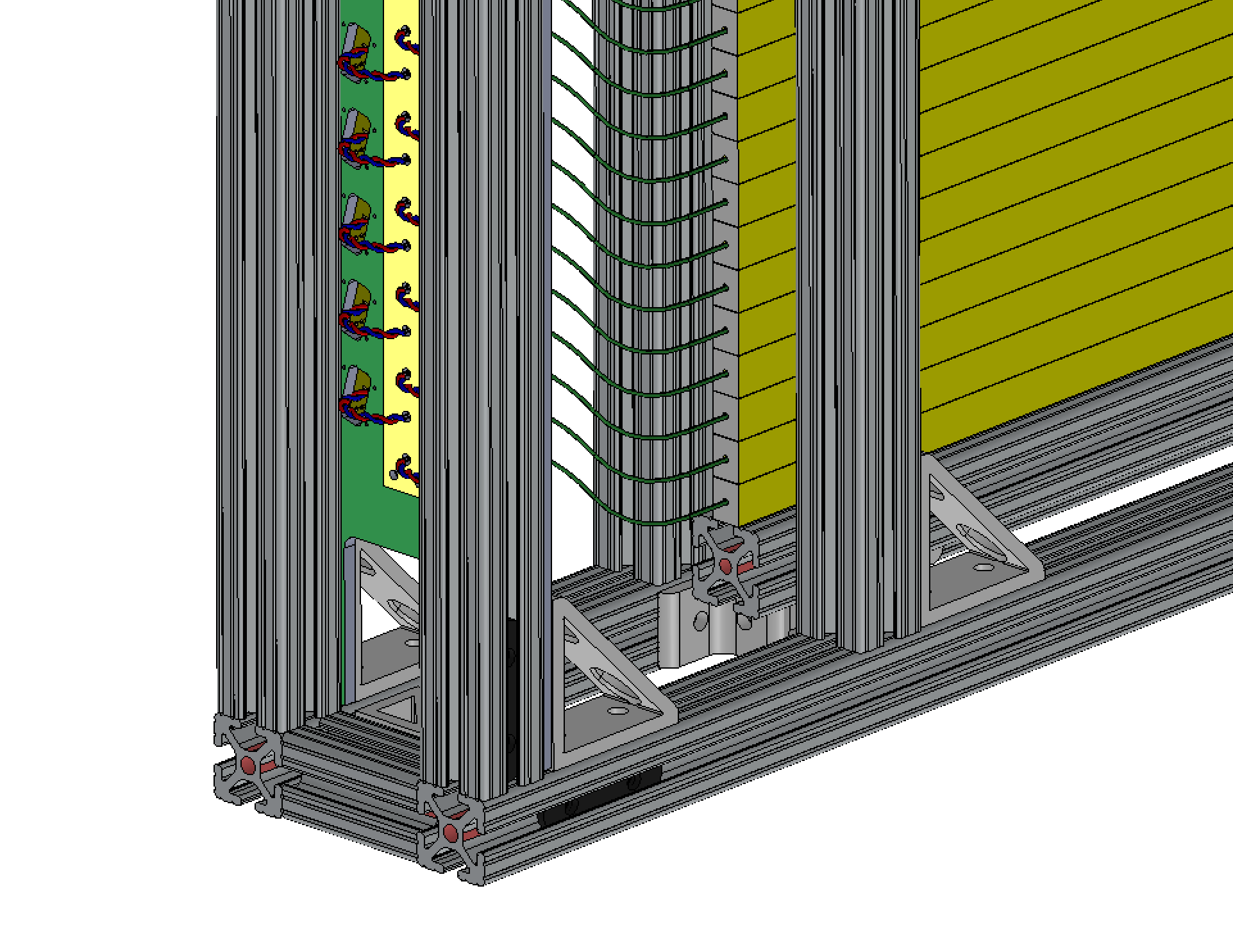
| The other side of the plate is shown here. SiPMs sit in square wells,
held inn place by a thin cover plate (yellow) [we did this rather than
epoxy the SiPMs in place]. Twisted pairs go to the preamp
boards, exposed through a hole.
I think for now, the holes on both the SiPM end and the preamp board end should be big enough for a 2-pin 1/10" connector. We can decide later if we solder both ends of the twisted wire pair, or have 1 or 2 connectors. |
|
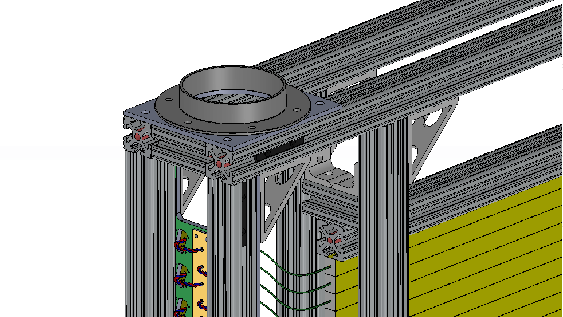
| A 4" flange on the top surface is the cooling air inlet. We can have flanges on the bottom, and something like this on the back face where the cables come out. |
|
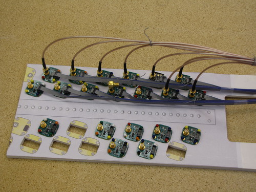
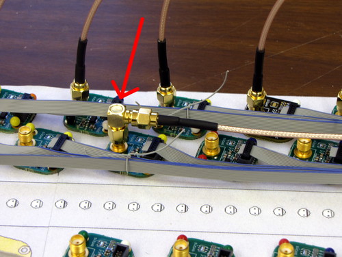 Mockup of one end of the '80 bars' plate, with a number of the
readout boards in place. The ribbons can be led low and along the
side, and the coaxes rise higher. Here, a few straight-connector coaxes
are put in place, but a better option is to use right-angle connectors.
|
|
In order to protect the back of the amplifier boards from shorting on the aluminum mounting plate, I cut some protective masks out of mylar (old overhead slides, 150 μm thick). Converted to pdf, eps, svg at VectorMagic.com, and traced in Inkscape: svg, pdf. I laser-cut the pdf on a Zing laser cutter (import into Adobe Illustrator, print, speed 60, power 15) Mask for the 2cm bars: png, pdf.
Easier path: import png to Inkscape, trace in a new layer (with linewidth
0.1px for cutting), save as svg file. This can be used directly on the cutter.
| |
| Fiber input side of the 80-bar unit. | |
| Back side | |
| On the 2cm-bar plate, the 80/20 posts partially (but barely, as indicated by the red lines) cover the openings for the preamps. This should not interfere with the red wires coming out. | |
|
back to 'hardware' | |
Hubert van Hecke Last modified: Fri Mar 24 12:16:21 MDT 2017
