| On the 80-bar units, there are two 3x3" spaces to feed through
80 coaxes, 80 ribbons and a few 1mm optical fibers.
If we use headers for the coaxes, is there enough space for this?
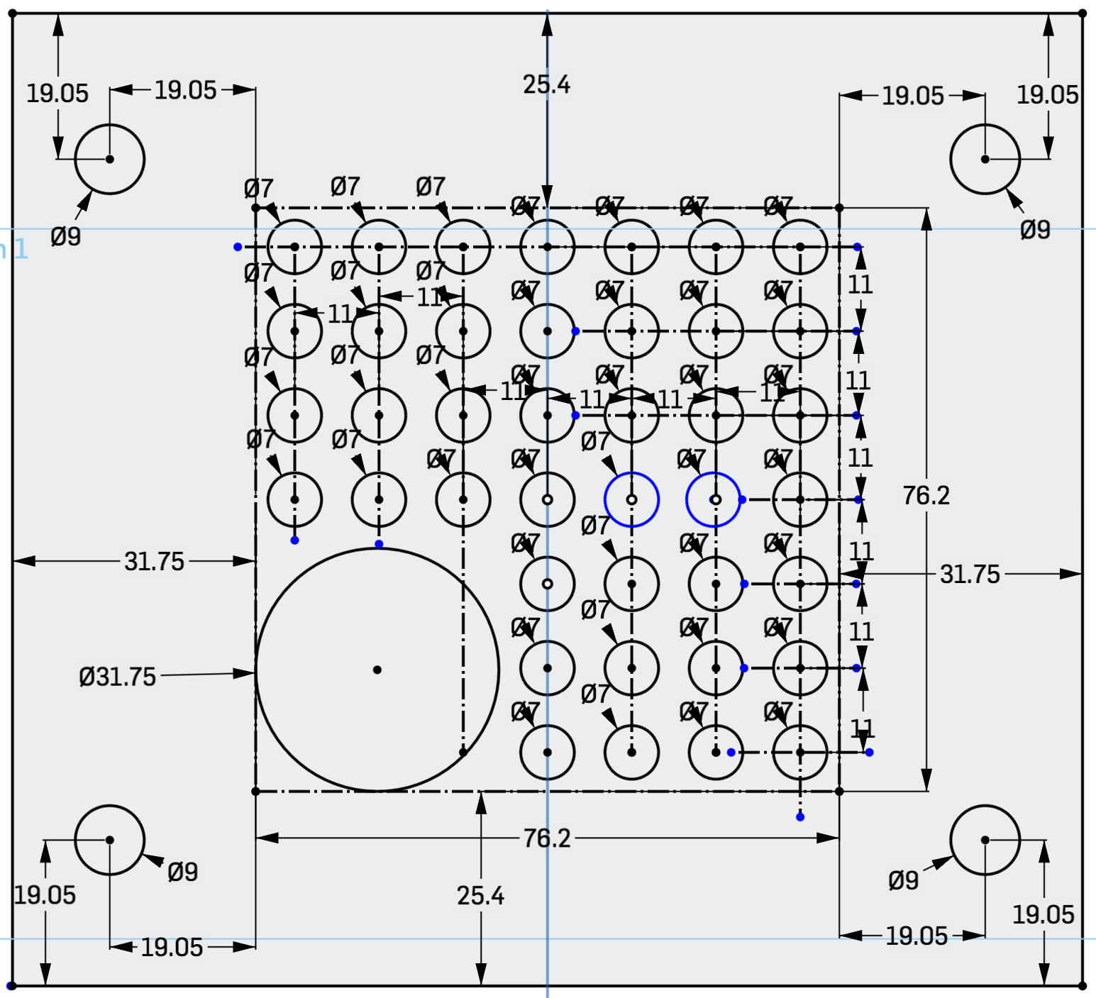
On the right is a mockup where the 3x3" space is outlined in blue. There is a 7x7 grid with 11 mm cells to place the coax headers. In one corner, a 3x3 portion of the grid is not occupied by these headers, but by a tube through which pass the ribbons and optical fibers. Note that 7x7-3x3=40, which is exactly what we need. I connected a handful of coax cables using the litle tool. There is just enough space to do this. The tube can be up to 1.25" OD (the one shown is 1"). Ideally we find one in black plastic, and after the ribbons are fed through, the remaining space is stuffed with black cloth or some such thing. | |
| Here is a drawing of this feedthrough plate. | 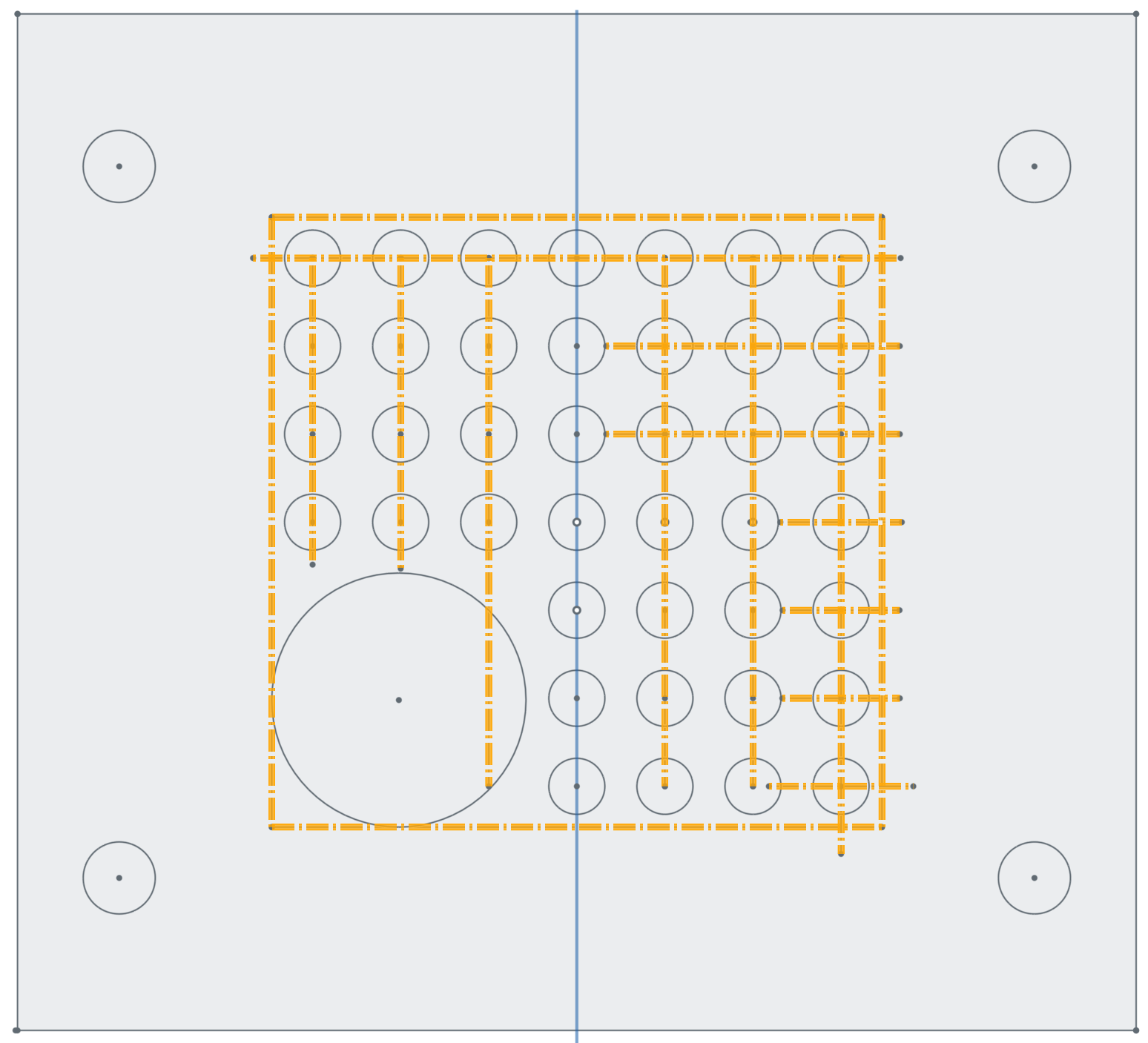
|
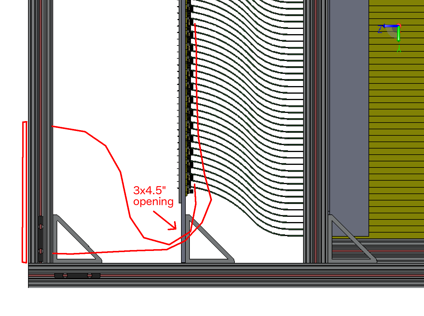
| Never mind. The situation is easier than described above. In the 80-bar boxes, the readout plane sits at the same distance from the end of the scintillator bars as in the 50-bar boxes. This means that in the 80-bar boxes there is 20cm of space from the readout plate to the back of the box, so we can fan things out to a space much larger than just 3x3". |
|
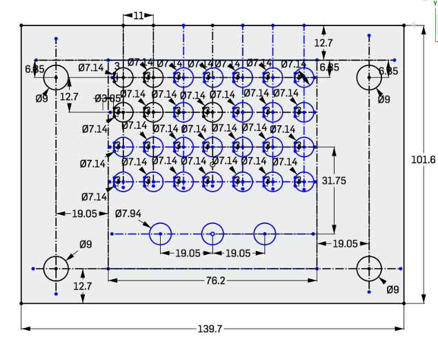
| This is the patch panel for the 1m units. There are 25 (+3 spare) holes for the coax bulkheads, and 3 spaces for the optical fiber bulkheads. This all fits inside a 3x3" area. | 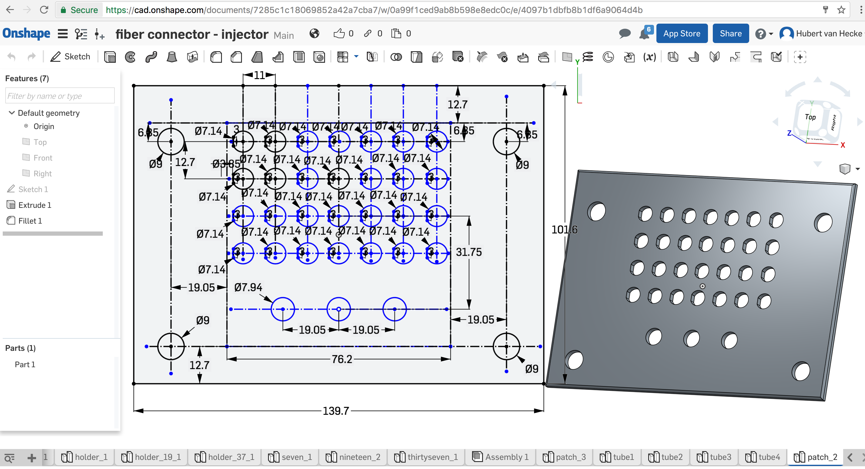
|
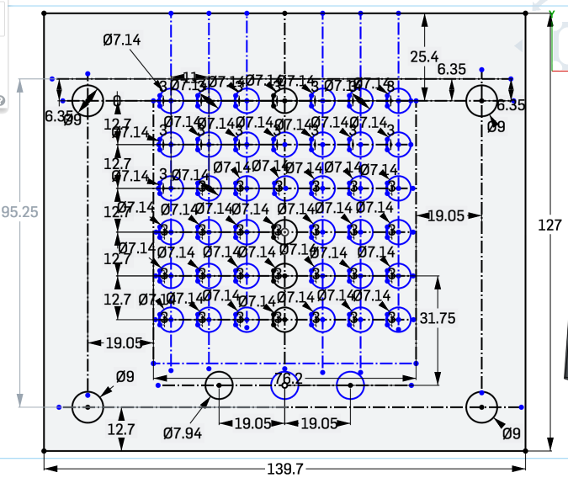
| This is the patch panel for the 80cm units. There are 40 (+2 spare) holes for the coax bulkheads, and 3 spaces for the optical fiber bulkheads. This takes up more than 3" vertically, but this does not matter. | 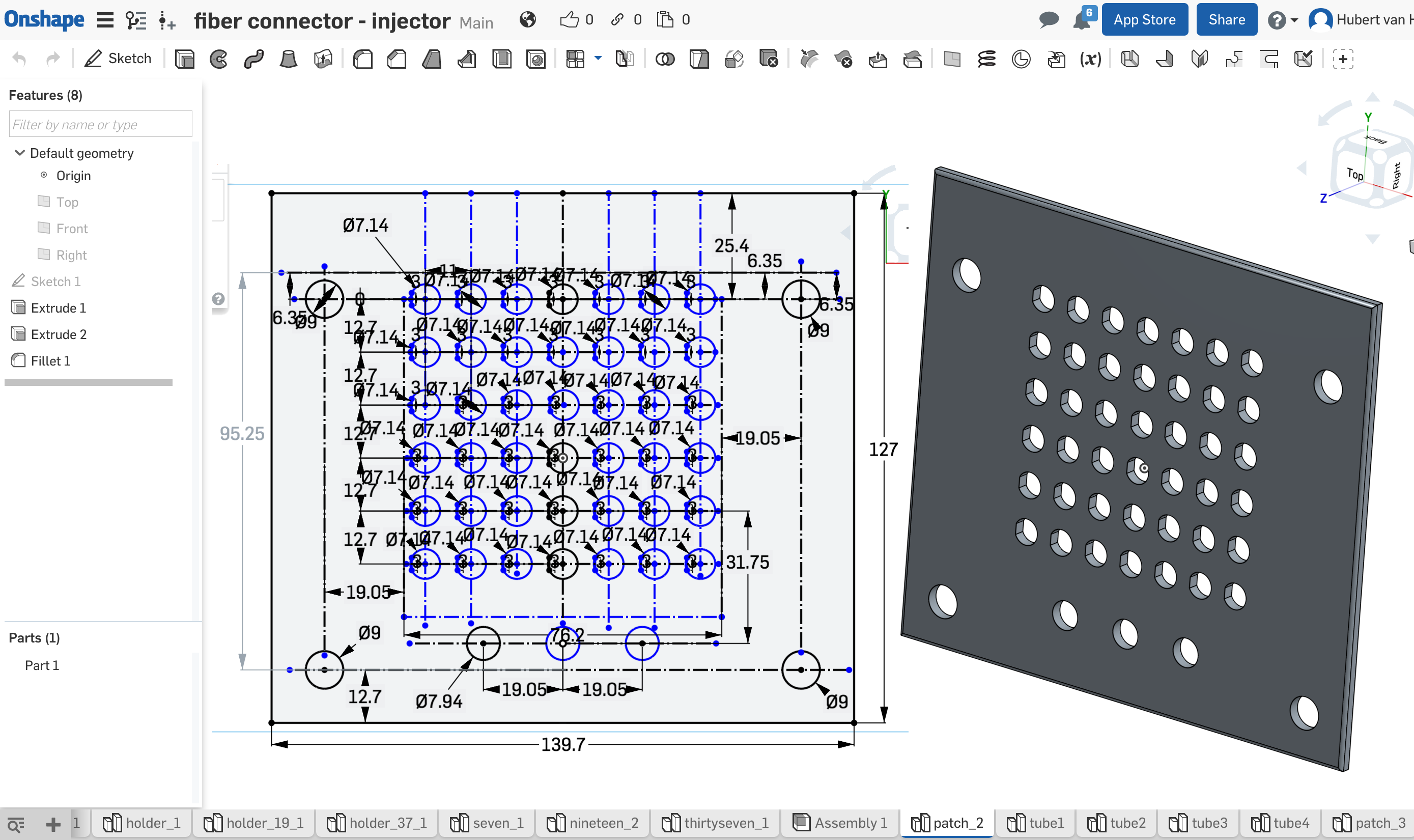
|
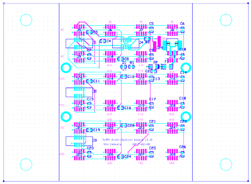
| The power ribbons go to a panel which serves as a patch panel
and a power distribution board (from
here)
24 connectors on the inside
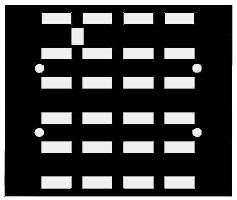
The patch panels are not completely opaque - there are vias all over.
I therefore made black paper masks to take care of that (cut on the laser
cutter at Make Santa Fe).
|
|
| Sketch of the end plate openings | 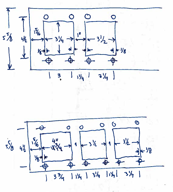
|
Hubert van Hecke Last modified: Fri Mar 24 12:05:19 MDT 2017
