gif
jpg
png
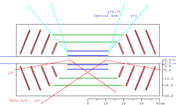
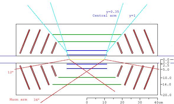
In the drawing below, a blue line is drawn at angle y=1, along the edge of
layers 2,3 and 4 of the barrel. The first two silicon endcaps are reduced to
start 1 cm
away from this line, in order to allow for support structures, cooling
services and power and signal cables. Also in blue are lines indicating the
central arm acceptance. On the bottom half, red lines indicate the muon arm
acceptance for an 'interaction diamond' of z=+-10 cm.
|
Formats available:
gif jpg png |
|
|
Cutaway view of the SVX detector, showing possible routings for
cabling and cooling of the barrel layers. Two possiblilities are shown:
the inner layer services are routed along the beampipe, while services
for layers 2, 3 and 4 are routed out along a direction roughly corresponding
to y=1. No support structures, or services for the encap silicon, are shown.
Click to enlarge --> |
| ||
|
Same cutaway view of the half-SVX, shown in perspective.
Click to enlarge --> |
Barrel only
| Click to enlarge -->
|
|
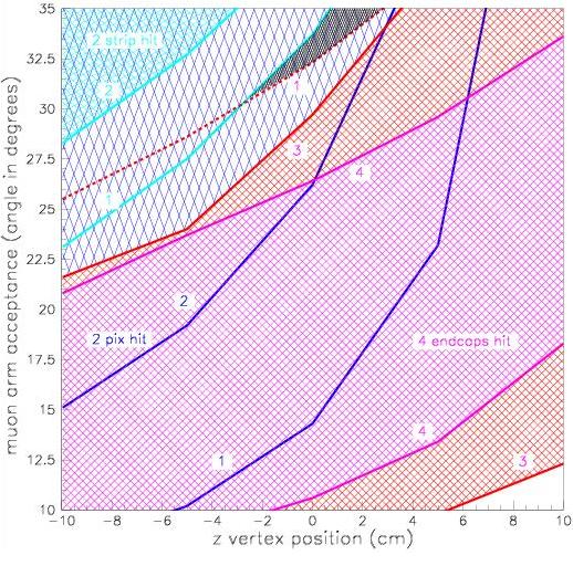
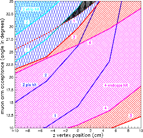 This plot shows the coverage of the Muon Arms, between 10° and 35°,
for event vertex positions between -10 and +10 cm.
This plot shows the coverage of the Muon Arms, between 10° and 35°,
for event vertex positions between -10 and +10 cm.
The area shaded in magenta shows the portion of the acceptance where tracks will traverse 4 silicon endcaps. Above an below are red hatched bands showing where tracks see just three endcaps, and the dotted line higher up shows where just one endcap is traversed. Above the dotted line no endcaps are hit at all. The blue lines and shadings show where barrel silicon is hit. Tracks above the blue line labeled [1] go through the first barrel pixel layer. Above the blue line labeled [2], both pixel layers are hit, and in light blue 1 and 2 strip strip layers are traversed. The black shaded area is where particles see only the barrel pixel layers and no barrel strip or endcap silicon. Formats available: png gif jpg ps kumac |