back
| (1) The problem is this: there is a bundle of light-emitting fibers, spread over a 20×20 mm square area, and a 3×3 mm avalanche photodiode (APD) for the detection of this light. | 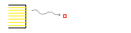
|
| (2) To first order, ALL emitted light can be directed to the APD with the use of one ideal positive lens: just image the fiber bundle onto the APD with magnification 3/20. A few rays are shown. | 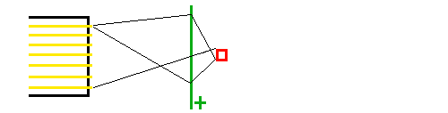
|
|
(3) In practice, the lens is not ideal, and its transverse size cannot extend
beyond the fiber bundle dimensions, as indicated by the blue lines. The
angular spread of the light coming out of the fibers is about ±30°, so
half of the light from fibers near the wall hits the wall and is lost.
(If we make the walls mirrored, those otherwise lost rays will appear to come from a virtual fiber positioned outside of the original bundle - if we want to capure those, the demagnification has to be even stronger - a losing game.) | 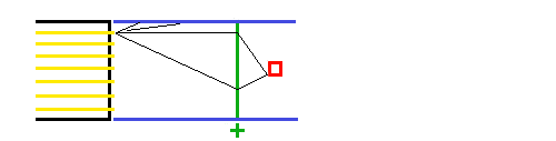
|
| (4) So the first thing to do is tip the outer light cones inward so we don't lose half of their light. This is done with a positive lens (1) placed right on the fiber ends. | 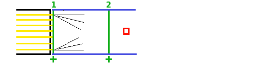
|
| (5) Since the rays (to first order) still have their origin in the same 20×20 mm plane, the same imaging lens (2) will now collect 100% of the rays from all fibers onto the APD. | 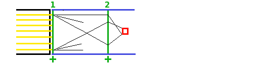
|
| (6) Start a G4 model. First, learn how to make a lens. This one is a polycone, with one flat face and one spherical face, made out of Acrylic. | 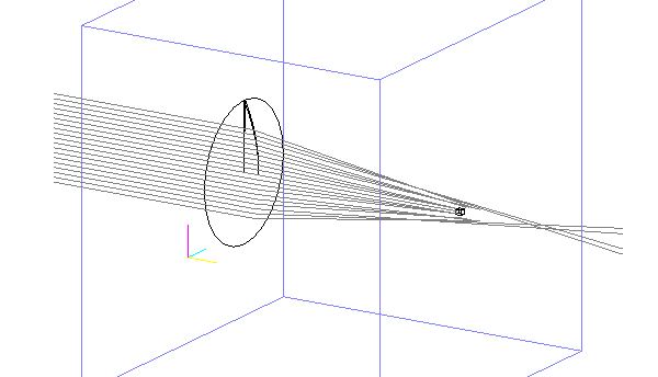
|
| (7) The focal length should be short, but now the lens has bad spherical aberations. | 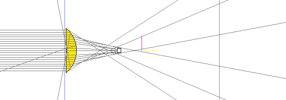
|
| (8) Add an empirical non-spherical term to the lens definition. Now most rays converge on the 3×3 mm detector. | 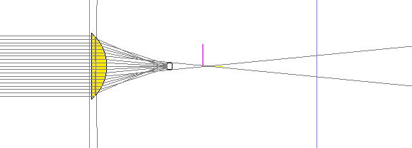
|
| (9) The first lens is meant to tip the light cone from the edge fibers inward. So make a cone of rays with a spread of about ±30° (says Paul). | 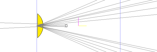
|
| (10) Move the cone to the top edge. Many rays are now lost to total internal reflection on the outgoing surface of the lens. | 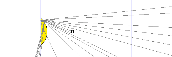
|
| (11) Reverse the lens. Not so bad. But note we now need some extra space on top because of the thickness of the lens. | 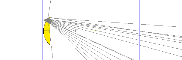
|
| (12) Compromise with a doubly-curved lens? (r1=40mm, r2=60mm) this is a little better, still some internal reflection. Lens 2 should be placed where (most of) both cones (generated at y=±13mm) are intercepted. | 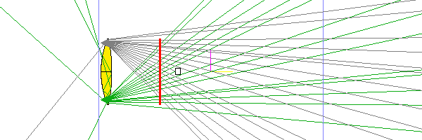
|
| (13) This shows a new problem: here lens2 is placed (radii 20,20mm, a2=-0.08), roughly in the right place, and even as fat as it is, the image is still pretty far away, meaning it will be much larger than the detector. Looks like it is impractical to shorten the focal length by enough. | 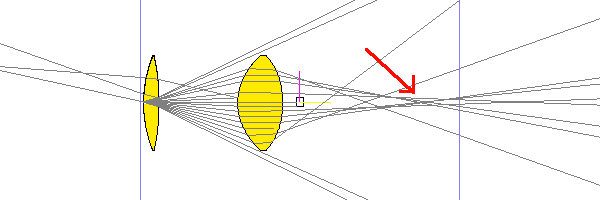
|
| (14) OK, plan B ! |
Hubert Van Hecke Last modified: Tue Dec 8 10:52:02 MST 2015