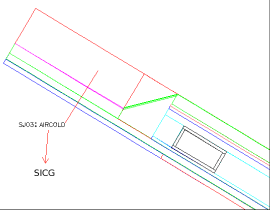
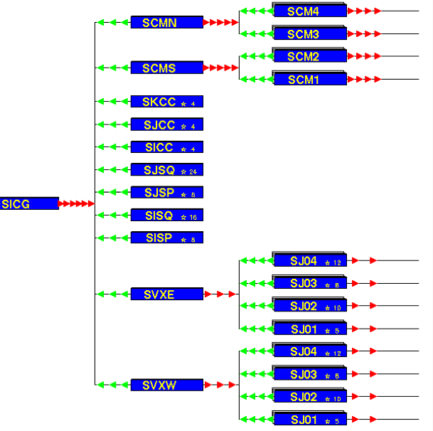
So I grouped the elements that make up a ladder together into a holder volume, so that you can move this single volume around.
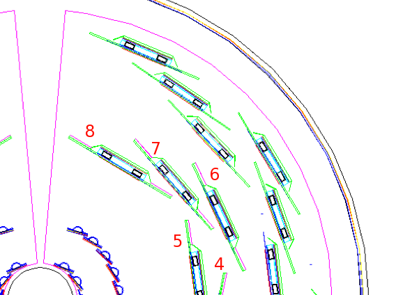
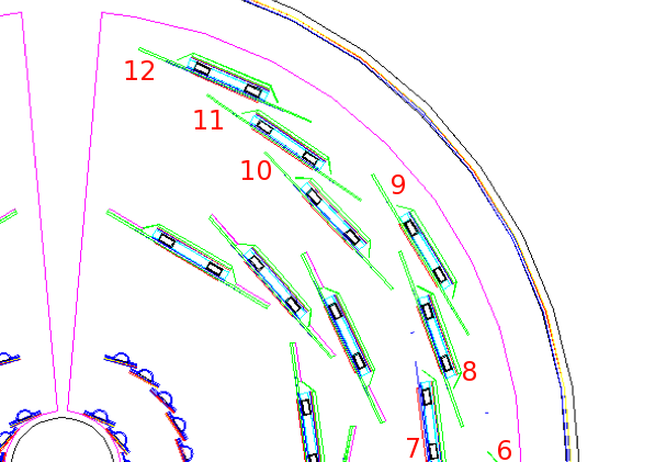
Right: In the new organization, all elements making up the layer 3 and 4 ladders are placed in a single holder volume, SJ03, SJ04 for layers 3 and 4, respectively.
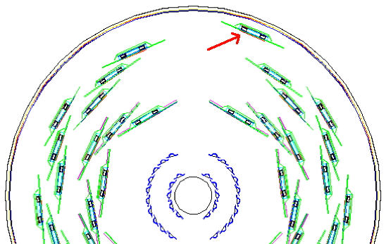
GEANT> dcut sien 3 .1 -7 -45 5 5
GEANT> satt * seen 1
GEANT> satt sj04 seen 0
GEANT> satt sp04 seen 0
GEANT> next; draw sj04 80 140 0 40  3 2.0 2.0
GEANT>       draw sj04 90  90 0 10 16 0.5 0.5
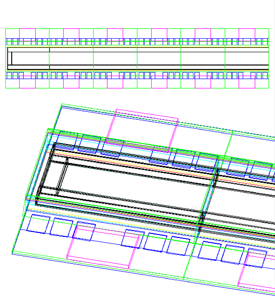
Group these together into SJ01 (for barrel 1) or SJ02 (for barrel2).
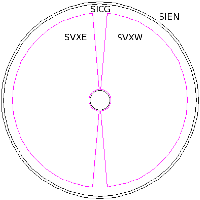
On the bottom, SVXE and SVXW are the barrel halves, each containing ladders SJ0x for barrels 1-4.
(The volumes in the middle, SKCC-SISP, are hoses, cables, manifolds, frames etc.)
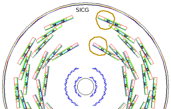
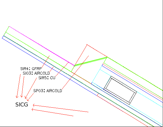
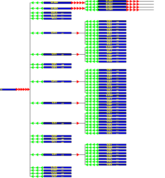 Here is the old organization, where many ladder elements were placed directly
into SICG. Almost impossible to read.
Here is the old organization, where many ladder elements were placed directly
into SICG. Almost impossible to read.
         vtx/fvtx    vtx        ladder          sensitive
 hall   enclosures  east/west   holder   stave  silicon
---------------------------------------------------------
 HALL   SIEN  SICG    SVXW      SJ01  1  SI01     SISN
 HALL   SIEN  SICG    SVXE      SJ01  6  SI01     SISN
 HALL   SIEN  SICG    SVXW      SJ02  1  SI02     SISN
 HALL   SIEN  SICG    SVXE      SJ02 11  SI02     SISN
 HALL   SIEN  SICG    SVXW      SJ03  1  SI03     SISN
 HALL   SIEN  SICG    SVXE      SJ03  9  SI03     SISN
 HALL   SIEN  SICG    SVXW      SJ04  1  SI04     SISN
 HALL   SIEN  SICG    SVXE      SJ04 13  SI04     SISN
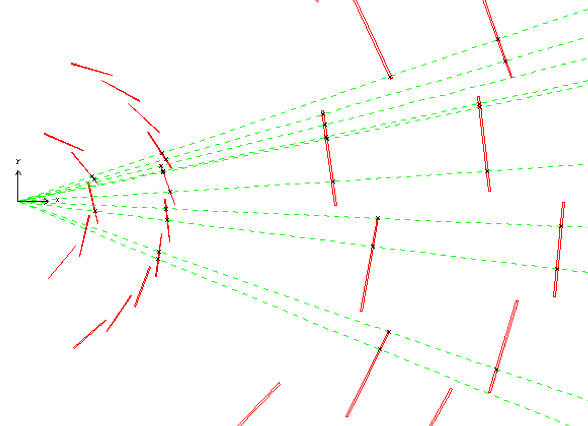
Single particle file cfmgmc.input
5 5 90 1 30 10 0. 0. 0. 0Picture:
  GEANT> satt * seen 0
  GEANT> satt sisn seen 1
  GEANT> cfm_sngp
  GEANT> ptrig 1
  GEANT> draw sicg 0 90 0 1 10 1 1
  GEANT> dxyz
  GEANT> dhits
  GEANT> daxis 0 0 0 1
By reading svxPISA.par, you can make the table below:
ladder center tilt
radius angle angle
barrel, ----------- ------------ -----------
ladder old new old new old new
------------------------------------------------------
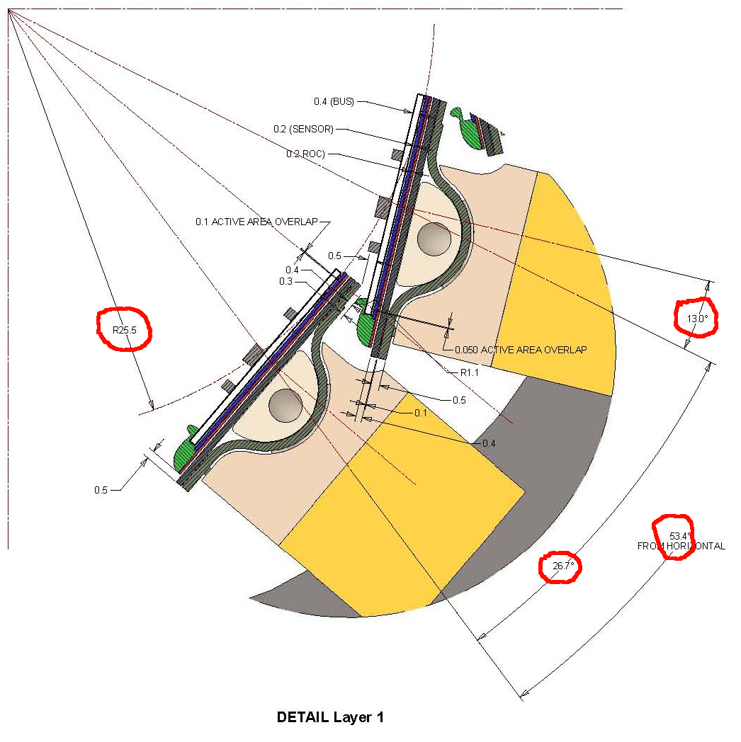
1 1 2.630 2.630 -53.400 -53.400 13.072 13.000
1 2 2.630 2.630 -26.700 -26.700 13.072 13.000
1 3 2.630 2.630 0.000 0.000 13.072 13.000
1 4 2.630 2.630 26.700 26.700 13.072 13.000
1 5 2.630 2.630 53.400 53.400 13.072 13.000
1 6 2.630 2.630 126.600 126.600 13.072 13.000
1 7 2.630 2.630 153.300 153.300 13.072 13.000
1 8 2.630 2.630 -180.000 180.000 13.072 13.000
1 9 2.630 2.630 -153.300 -153.300 13.072 13.000
1 10 2.630 2.630 -126.600 -126.600 13.072 13.000
-------------------------------------------------------
(output from compare1.f, which reads svxPISA.par)
This verifies that the barrel 1 ladders are placed correctly in the new organization. Note the tilt angle used to be off by a little.
By reading svxPISA.par, you can make the table below:
  barrel ladder sensor  R       angle      tilt
  ----------------------------------------------
    2      1      1   5.1300   -61.2000  13.0203  <- not 13.0000
    2      2      1   5.1300   -47.6000  13.0198
    2      3      1   5.1300   -34.0000  13.0202
    2      4      1   5.1300   -20.4000  13.0201
    2      5      1   5.1300    -6.7999  13.0202  <- not 5.12 cm
    2      6      1   5.1300     6.7999  13.0203
    2      7      1   5.1300    20.3999  13.0200
    2      8      1   5.1300    34.0000  13.0199
    2      9      1   5.1300    47.6000  13.0194
    2     10      1   5.1300    61.2000  13.0195  <- not 61.5000

    2     11      1   5.1300   118.8001  13.0195
    2     12      1   5.1300   132.4000  13.0206
    2     13      1   5.1300   146.0000  13.0199
    2     14      1   5.1300   159.6000  13.0199
    2     15      1   5.1300   173.2001  13.0203
    2     16      1   5.1300  -173.2001  13.0199
    2     17      1   5.1300  -159.6001  13.0197
    2     18      1   5.1300  -146.0000  13.0199
    2     19      1   5.1300  -132.4000  13.0195
    2     20      1   5.1300  -118.8001  13.0200
------------------------------------------------
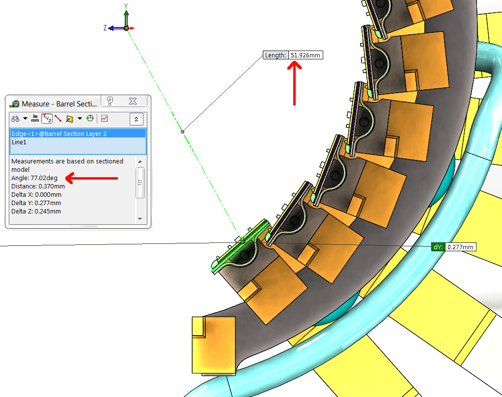
Note the discrepancies. What is going on?
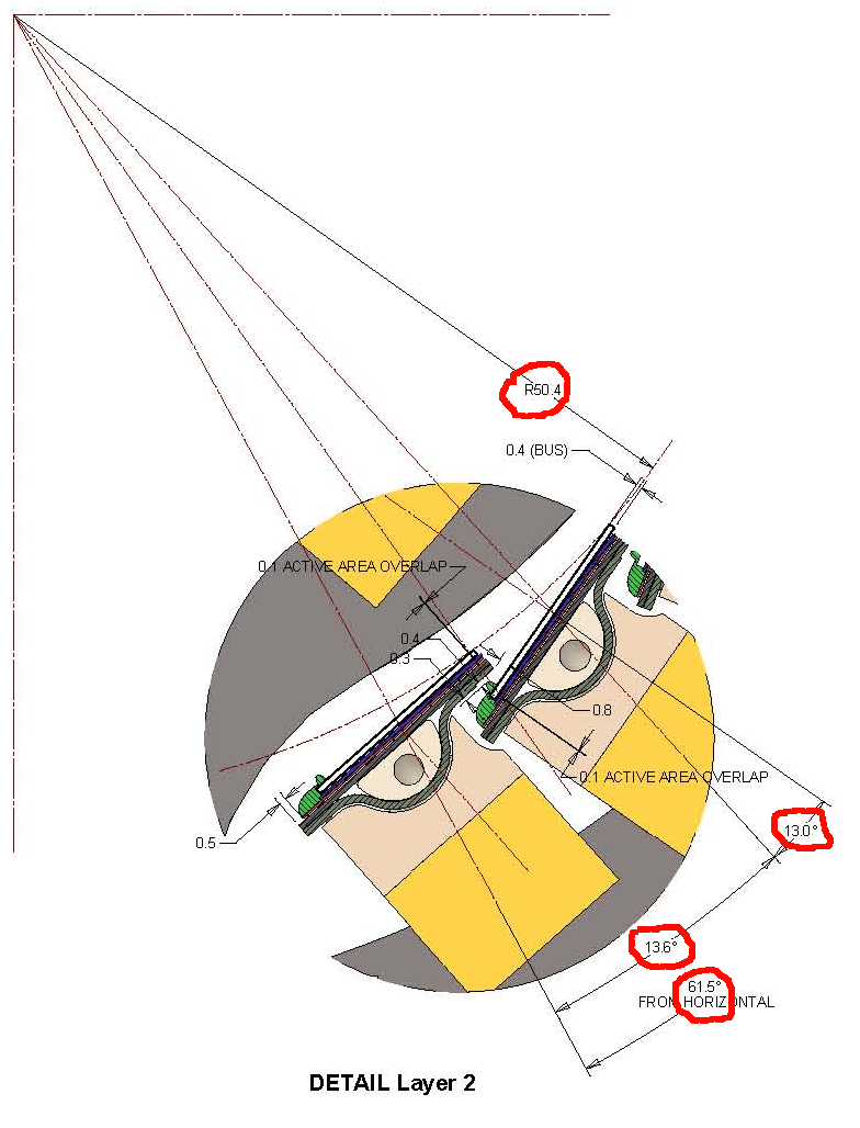
(12) So Walt and I went to the VTX 3D model and measured the distance from the origin to the center of the silicon sensor (51.926 mm), and the angle of the sensor w.r.t. the radius to the silicon center (77.02°). This means the tilt angle is 12.98°, not 13.02°. The radius of the circle tangent to the silicon surface is now 50.55 mm (was 50.4). The ladder-to-ladder angle was measured to be 13.626°
Entering these values in phnx.par, we now get:
           ladder          center            tilt
           radius          angle             angle
barrel,  -----------     ------------     -----------
ladder   old     new     old      new     old     new
-------------------------------------------------------
 2  1   5.130   5.193  -61.200  -61.317  13.057  12.980
 2  2   5.130   5.193  -47.600  -47.691  13.057  12.980
 2  3   5.130   5.193  -34.000  -34.065  13.057  12.980
 2  4   5.130   5.193  -20.400  -20.439  13.057  12.980
 2  5   5.130   5.193   -6.800   -6.813  13.057  12.980
 2  6   5.130   5.193    6.800    6.813  13.057  12.980
 2  7   5.130   5.193   20.400   20.439  13.057  12.980
 2  8   5.130   5.193   34.000   34.065  13.057  12.980
 2  9   5.130   5.193   47.600   47.691  13.057  12.980
 2 10   5.130   5.193   61.200   61.317  13.057  12.981
 2 11   5.130   5.193  118.800  118.683  13.057  12.981
 2 12   5.130   5.193  132.400  132.309  13.057  12.980
 2 13   5.130   5.193  146.000  145.935  13.057  12.980
 2 14   5.130   5.193  159.600  159.561  13.057  12.980
 2 15   5.130   5.193  173.200  173.187  13.057  12.980
 2 16   5.130   5.193 -173.200 -173.187  13.057  12.980
 2 17   5.130   5.193 -159.600 -159.561  13.057  12.980
 2 18   5.130   5.193 -146.000 -145.935  13.057  12.980
 2 19   5.130   5.193 -132.400 -132.309  13.057  12.980
 2 20   5.130   5.193 -118.800 -118.683  13.057  12.980
-------------------------------------------------------
(output from compare1.f, which reads svxPISA.par)
Note the Barrel2 ladders have moved in r, phi and tilt.
            ladder          center            tilt
            radius          angle             angle
 barrel,  -----------     ------------     -----------
 ladder   old     new     old      new     old     new
 -------------------------------------------------------
  3  1  11.765  11.765  -61.410  -61.410  0.000   0.000
  3  2  10.360  10.387  -43.370  -43.370  0.000   0.000
  3  3  12.848  13.143  -26.210  -26.210  0.000   0.000
  3  4  11.765  11.765  -10.150  -10.150  0.000   0.000
  3  5  10.360  10.387    7.890    7.890  0.000   0.000
  3  6  12.848  13.143   25.050   25.050  0.000   0.000
  3  7  11.765  11.765   41.110   41.110  0.000   0.000
  3  8  10.360  10.387   59.150   59.150  0.000   0.000
  3  9  10.360  10.387  120.850  120.850  0.000   0.000
  3 10  11.765  11.765  138.890  138.890  0.000   0.000
  3 11  12.848  13.143  154.950  154.950  0.000   0.000
  3 12  10.360  10.387  172.110  172.110  0.000   0.000
  3 13  11.765  11.765 -169.850 -169.850  0.000   0.000
  3 14  12.848  13.143 -153.790 -153.790  0.000   0.000
  3 15  10.360  10.387 -136.630 -136.630  0.000   0.000
  3 16  11.765  11.765 -118.590 -118.590  0.000   0.000
 -------------------------------------------------------
After code fixes, the radii have changed by 0.27, 0, 2.95 mm for inner, middle, outer ladders, and match the as-built drawings.
From compare3.f
Silicon thickness (from phnx.par) 0.625 mm.
Raw numbers from the as-built 3-D model, distances from the front face
of the silicon to (0,0,0):
Front surface Si volume center
---------------------------------------
inner 103.56 mm 103.87 mm
middle 117.34 mm 117.65 mm
outer 131.13 mm 131.44 mm
---------------------------------------
(14) Layer 4:
ladder center tilt
radius angle angle
barrel, ----------- ------------ -----------
ladder old new old new old new
-------------------------------------------------------
4 1 15.473 15.546 -65.130 -65.130 0.000 0.001
4 2 16.687 16.687 -52.690 -52.690 0.000 0.000
4 3 17.901 17.828 -41.120 -41.120 0.000 0.000
4 4 15.473 15.546 -29.080 -29.080 0.000 0.000
4 5 16.687 16.687 -16.640 -16.640 0.000 0.000
4 6 17.901 17.828 -5.070 -5.070 0.000 0.000
4 7 15.473 15.546 6.970 6.970 0.000 0.000
4 8 16.687 16.687 19.410 19.410 0.000 0.000
4 9 17.901 17.828 30.980 30.980 0.000 0.000
4 10 15.473 15.546 43.020 43.020 0.000 0.000
4 11 16.687 16.687 55.460 55.460 0.000 0.000
4 12 17.901 17.828 67.030 67.030 0.000 0.000
4 13 17.901 17.828 112.970 112.970 0.000 0.000
4 14 16.687 16.687 124.540 124.540 0.000 0.000
4 15 15.473 15.546 136.980 136.980 0.000 0.000
4 16 17.901 17.828 149.020 149.020 0.000 0.000
4 17 16.687 16.687 160.590 160.590 0.000 0.000
4 18 15.473 15.546 173.030 173.030 0.000 0.000
4 19 17.901 17.828 -174.930 -174.930 0.000 0.000
4 20 16.687 16.687 -163.360 -163.360 0.000 0.000
4 21 15.473 15.546 -150.920 -150.920 0.000 0.000
4 22 17.901 17.828 -138.880 -138.880 0.000 0.000
4 23 16.687 16.687 -127.310 -127.310 0.000 0.000
4 24 15.473 15.546 -114.870 -114.870 0.000 -0.001
-------------------------------------------------------
After code fixes, the radii have changed by 0.73, 0, 0.73 mm for inner, middle, outer ladders, and match the as-built drawings.
From compare3.f
Silicon thickness (from phnx.par) 0.625 mm.
Raw numbers from the as-built 3-D model, distances from the front face
of the silicon to (0,0,0):
Front surface Si volume center
---------------------------------------
inner 155.143 mm 155.455 mm
middle 166.555 mm 166.868 mm
outer mm mm
---------------------------------------
(15) Summary:
- The VTX Geant3 volume tree was reorganized such that
- All components that make up a ladder are placed together in a
holder volume (one per ladder)
- West VTX ladders are placed in SVXW, east in SVXE, and these
two are places in the (F)VTX cage.
- The VTX Pisa code can read a SQL database record containing small
displacements for each ladder, and for each of the VTX halves.
- The placement of the ladders was checked against the as-built
engineering drawings, and the code was corrected to match this geometry,
resulting in shifts and rotations wrt the previous version of the code.
(16) How to interface with the alignment system?
- PISA produces an output file svxPISA.par, which contains a description
of the position and orientation of each SVX sensor chip (x,y,z and
rotation matrix).
- svxPISA.par is read in by the offline code to establish the VTX
geometry.
- The alignment software operates on this geometry, and produces a new
svxPISA.par.
Now what is needed is a way to read this new file into PISA, so that
simulations can be run that match the data. This file cannot be used directly
to construct the VTX. However, by comparing svxPISA.par from an unmodified
PISA run with the version produced by the alignment software, you can easily
find the delta-x,y,z between the two files. These deltas can then be used
by PISA to position the ladders. So if you give PISA these two files, it can
produce the modified geometry. The procedure is:
- Run PISA unmodified to make a 'clean' svxPISA.par (just start/stop,
no need to generate any events)
- Run PISA again, this time giving it both the 'clean' and the
modified versions of svxPISA.par.
Also see: Fix the offline software to
recognize the new hierarchy.