Cartoons of an assembly that allows sequential mounting of barrel layers
1,2 and 3,4, and independent mounting of endcaps.
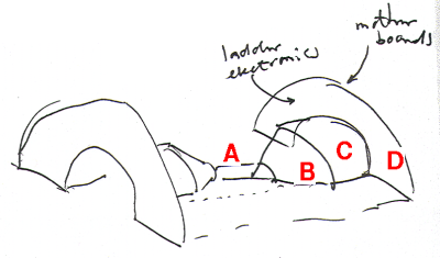
Start with an assembly consisting of
- beam pipe cover
- barrel ladder support cone
- endcap radial outer cover cylinder
- endcap electronics carrier board
You can now mount the barrel ladders. Ladders are fixed to support
cone B, cables are guided along B and C, and electronics are mounted to
the inside of the carrier board D.
| 
|
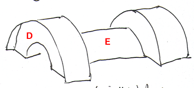
| An outer cover is mounted over the assembly, which can
have either 2 or 4 layers in it. The outer surface of the carrier board is
still visible.
| 
|
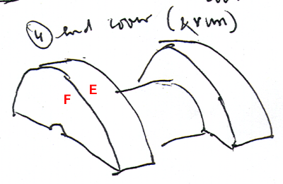
| An endplate cove F is mounted. Barrel is ready to run.
| 
|
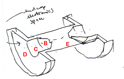
Alternatively, you can turn the assembly over, and
mount the endcaps inside cone B and cylinder C, with electronics mounted
on the other side of carrier board D.
After this, mount the endplate F (from the previous picture). In addition, you
can add beampipe covers over the endcaps. These go between beampipe cover
A (from the top picture) to the endplates F.
| 
|
The carrier boards D are the main anchor plates. These can be made very
stiff and hold the connections to the external mount points.
For strength, a series of posts going radially out from the joint between B
and C can connect to outer cover C. The posts need to go in between barrel
cables, pipes etc. Also posts parallel to the beampipe connecting outer cover
E to the carrier boards, at the inner radius (~20cm) of E.
The halves have little strength against twisting around the z-axis, but are
very strong against twist after the two halves are locked together.
Last update 17 June 2005 - HvH