The FVTX is constructed as 4 identical quadrants. Arrange cabling numbering such that it is identical for each of the quadrants. This means that for example if a test station for one quadrant is set up, the next quadrant can be hooked up without having to rearrange the cable order.
| This is the PHENIX global coordinate system, with +z=North, +y=up and therefore +x=West. Global phi starts at x=0 and rotates toward +y. | 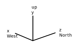
|
The quadrants are numbered from x=low, z=low to x=high, z=high. Therefore the quadrant numbers are:
quadrant  location  numeric
  1         SW        00
  2         SE        01
  3         NW        10
  4         NE        11
Cables, boards etc. can be labeled SWxxx through NExxx or 1xxx through 4xxx. For labeling purposes, the SW-NE is clearer than 1-4 or 00-11, so I will pick this convention. | 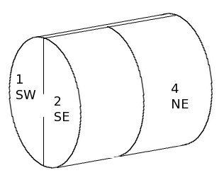
|
| Next we have to decide on the numbering along the perimeter: top to bottom or v.v. The wedge
numbering on each half-disk proceeds in a clockwise direction when facing the upstream or downstream surfaces, so
that for quadrant 1 this is in the +phi direction for the downstream (-z) face, and -phi for the upstream (+z)
face. So wedge numbering does not give us a preferred direction.
However the ROC's themselves use numbering that runs in +phi when facing the board. Therefore we choose the ROC and cable numbering such that on the South side, ordering is along -phi, but in the North along the +phi direction. In addition, in keeping with earlier rulings, we start counting at 0. | 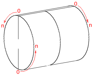
|
| ROC board numbering:
The ROC boards will come with their own production sequence numbers. Here we define the ROC board position numbering. The orientation is as we would see the quadrant in the assembly fixture. The sequence is as defined in the previous figure. | 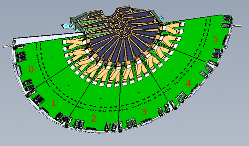
|
| There are 4 fiber connections per ROC board. These are labeled quadrant(SW-NE) - roc_position(0-5) - fiber_number(0-3). The fiber labels would run from SW-0-0 through NE-5-3. Since all are numbers are single digits, we could omit the hyphens, so the fiber labels could be shortened to SW00 through NE53. A few pictures down I re-introduce the hyphen for the bias connectors. So for uniformity, I will use labels XY-n, where X=SE-NW, Y=0-5. | 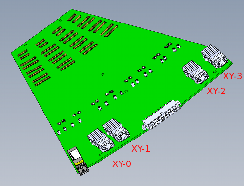
|
| There is only one power connector per board, so following the same convention, these would be labeled XY-0, where X is the quadrant (SW-NE) and Y is the ROC position. | 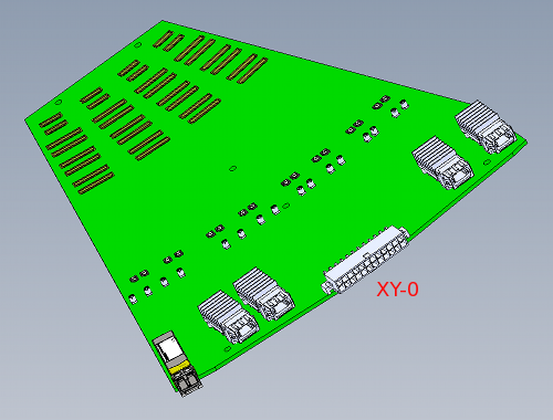
|
| The bias connectors are labeled the same way. Since there are 16 of them, a hyphen is in order. Labels would run from SW0-0 through NE5-15. | 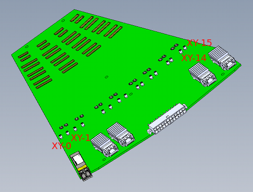
|
| The slow-controls connector is labeled XY-0 where X is the quadrant (SW-NE) and Y is the ROC position. Labels run SW0-0 through NE5-0. | 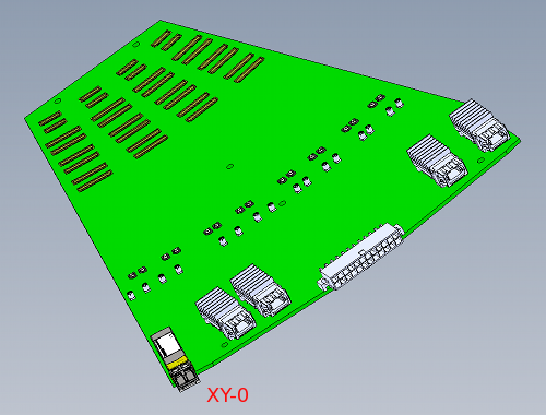
|
| There are 4 wedge power connectors (J1, J1A, J2, J2A), one for each of the 4 stations, respectively. | 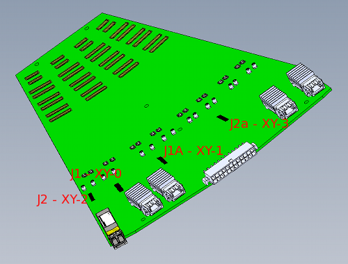
|
| This shows station 2, in the same orientation as the previous figures. As can be seen, the wedge numbering
(starting with 0) starts with the 'upstream low' module (highlighted in green), followed by the downstream high (1),
upstream high (2, not visible in this view), and the fourth one is downstream low (3).
So for stations 2,3,4: wedge ROC pos cable drawing --------------------------------------------- 0 1 2A 3x02 upstream/low 1 0 1A 3x01 downstrm/high 2 3 2B 3x04 upstream/high 3 2 1B 3x03 downstrm/low ---------------------------------------------For station 1, exchange upstream←→downstream and low←→high. | 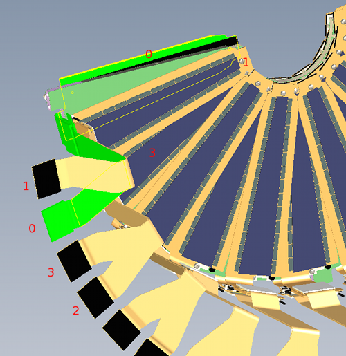
|