MVD Signal/noise problem
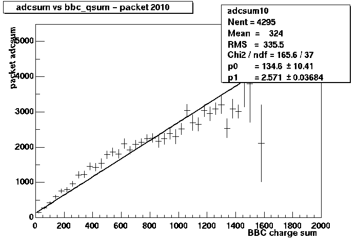
This problem is really a problem with the signal more than the noise. For many MCMs, the signal is much smaller than normal while the noise is typical. The following plot

shows the correlation between the ADC sum in a "good packet" and the ADC sum in the BBC. The next plot:

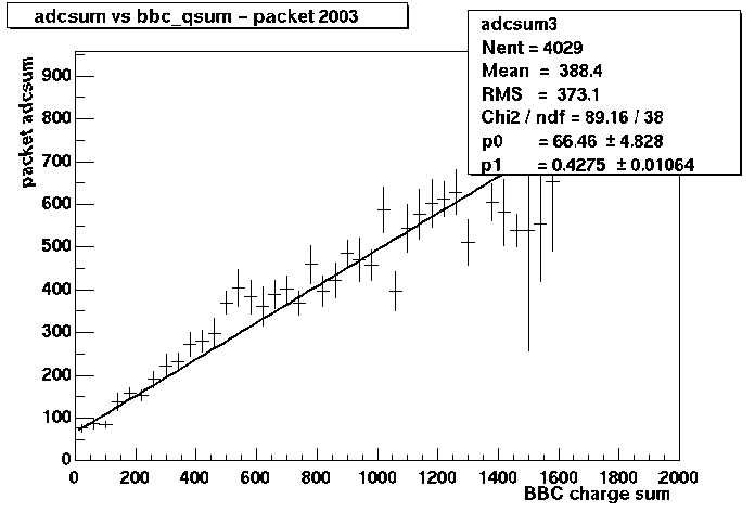
shows the same correlation for a packet with poor signal to noise.
There is still a clear correlation, but the slope is much less
because the ADC signal from this MVD packet is much smaller.
There are many similar examples. There plots come from
a much
more extensive web page created by Allan.
I can think of several possible reasons for this problem
1) problem with bias voltage
2) level-1 timing wrong in some MCMs
3) preamplifiers "hit the rail" and are not reset often enough
There are arguments for an against each of these possibilities and the real problem may be some combination of these and other problems.
Problem with bias voltage?
The problem does not seem to be that there is no bias voltage reaching
the MCMs with poor signal to noise. The evidence is from one MCM on
which the Silicon detector will not hold the bias voltage. Its bias voltage
was turned off during the run, but in some cases it was still read out.
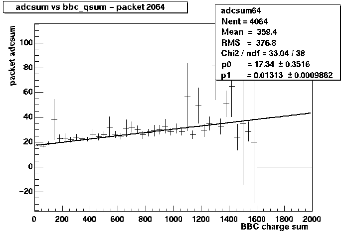
Here is the correlation between the ADC sum from this MCM and the BBC ADC sum:

The slope is much lower than is typical for the channels with poor signal to noise. There is essentially no signal. This is only one example, but it seems that at least part of the bias voltage is reaching the MCM+Si detector assemblies which have poor signal to noise. Perhaps they are under-biased? Perhaps there is some problem in the bias voltage distribution. Problems with the bias voltage distribution can be tested easily, we just need to do some measurements. I suspect some problems in the distribution system because there are ~3 bias channels which will not hold voltage even though there is no detector connected to them.
While investigating this possibility, we need to find the cause of the HV channels that trip. Packet 2064 is affected by this -- so are some other channels which are not actually connected to a detector. I suspect a problem inside the HV distribution or maybe in the cables.
Level-1 timing wrong in some MCMs?
I am concerned about this problem because of some strange observations
during the tests of DCIMs in the side room of Bldg 1008. I noticed
that the packets we read out with each event were divided into two groups.
One group would have "beam clock number" N and the other group would
have "beam clock number" N+1. My suspicion is/was that this was caused
by a problem in the timing of the level-1 trigger vs. the beam clock
on our MCMs. These two signals are in phase -- meaning that the rising edge
of the level-1 trigger arrives at the same time as the rising edge of the
beam clock. The "Address List Manager" (a Xilink FPGA on the MCM) counts
backwards by 45 beam clocks to pick the correct pair of AMU cells for
the "pre" and "post" samples. My concern is that some FPGAs may count
the beam clock which arrives at the same time as the level-l before
counting backwards and some may count not count this beam clock.
The problems with this explanation are
1) I tried to find an example of this problem by looking for a difference
in the timing of
the level-1 delay curve for different packets. I was not able to find
an example which was consistent with my suspicions. Later, Sangsu
did a similar search -- also without success.
2) In the real data, I do not see the same pattern of beam clock
numbers. Instead all the packets seem to have different numbers.
I think this may have to do with the order the various arcnet
commands and mode bits are sent to the different MCMs. Some of
these commands reset the beam clock number, but are not sent
to all MCMs simultaneously. This is a separate problem which
should be fixed.
Even if this problem is not occurring, I believe that something needs to be done to change the relative timing of the level-1 and beam clock signals -- or to verify that this is not a problem.
Preamplifiers "hit the rail" and are not reset often enough?
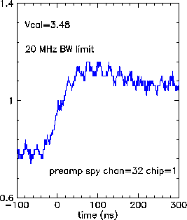
The output from our preamps look something like this on an oscilloscope:

The rising edge, which never falls back to the original voltage is caused by a "hit" on this channel. The preamp needs to be reset from time to time. This is done via a mode bit command through the GTM. The details of the shape of this pulse are set via serial controls to the preamplier. Specifically, the DAC called "Vfb" can be set to give the behavior seen in the plot above or to pull the signal back down to baseline. We did a series of runs with Vfb changed from 3.0 V to 2.5 V to see if it helped with this problem. However, I do not have the list of the runs numbers with this change and I have not looked into the differences if any.