MCM alive


6 May 99
Today the first production MCM was tested, and found to be generally healthy at first sight. This MCM is one of a batch of 12 that was received at Los Alamos. After thorough testing, the remaining MCM's will be produced at Lockheed-Martin, for a total of 176.

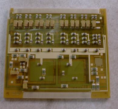
Shown in the picture on the right is the MCM in question. It measures 48x43 mm, which is about 2/3 of a credit card, and services 256 silicon strips or pads. The Silicon signals will arrive at the top. What is visible is mostly surface-mount capacitors. The top half holds 2 rows of 8 chips: 32-channel AMU-ADC's, followed by 32-channel ADC's. Under the large green squares in the foreground are the 2 Xilinx FPGA's, and along the bottom of the MCM are 50 traces for communication to and from the outside world.

This is a view of the test setup. Part of the MCM is visible at the bottom of the picture. Wirebonds connect it to a short output cable. Since the bonds have not yet been encapsulated, they are covered up with the white foam protector.
Between the MCM output cable and the Power/Communication board along the top of the picture is a temporary board which allows us to look at the communications to/from the MCM.


Here is a partial list of things we checked so far (6 May 99 19:00):
  1. The ADC_CLK_EN signal had the correct width (it comes to one of 8 test points on the surface of the MCM) for our 10 bit digitization and the RAMP (also a test point) responded to changes in the IREF DAC in the serial string.

    This means that the ADC control signals and clock seem to be working correctly.

  2. The various clocks (1X beam, 4 X beam, PECL + and -) all looked good:


  3. Power usage was more or less as expected -- roughly 2 Watts/MCM (what we expected) plus about 3 Watts per power-comm board (this may be a surprise).
  4. The serial string goes into the system.
  5. The Xilink code loads normally.
  6. The system responds to level 1 triggers with reasonable looking data packets. The packet length is appropriate for our choice of correlator on/off mode (i.e. either 256 or 512 ADC values). The header words look correct. The horizontal parity bits are correct. There is a problem with the vertical parity word. This is likely a Xilinx software problem related to the chip's speed grade.
  7. All the various voltages and control signals had appropriate levels when checked.
There are still some (soluble) problems. The surface mount components (mounted with conductive epoxy) had problems -- the epoxy did not seem to be properly cured. Some components fell off and we removed others as a preventative measure. These were filter capacitors and did not stop he basic functioning of the MCM. The conductive expoxy had shorted one PECL clock to +5V and stopped it from working. This problem wasted most of the afternoon. The epoxy problem is easily solvable.

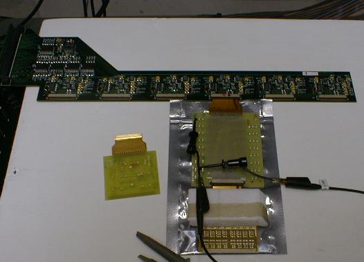
There seems to be an offset (one bit) we think in the serial string alignment. We believe we know where this comes from and it is easily fixed in software.

We have not done any serious signal/noise tests.


back