Table of Contents
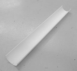
I. Fabricating the inner Rohacell cover
![]() B. Procedure
B. Procedure
II. Assembling the inner RF enclosure
![]() B. Procedure
B. Procedure
III. Installing the inner RF enclosure
![]() C. Procedure
C. Procedure
![]()
![]()
Part I. Fabricating the Inner Rohacell Cover
|
Part I, A.
The Materials Needed to Fabricate the Inner Rohacell Cover
- one 3mm thick sheet of Rohacell IG-71 measuring at least 30" x 7.25"
- a ruler, meter stick, or tape measure (preferably a T-square)
- a marker
- a razor blade or X-acto knife
- the inner enclosure forming jig
- an air-circulating oven large enough to easily fit the inner enclosure forming jig
- a watch or timer
- heat resistant gloves (preferably ones with fingers that are not clumsy)
- a plastic bag big enough to hold the 30" x 7.25" Rohacell sheet
- four (4) C-clamps with a jaw space of at least 2.5"
Part I, B.
The Procedure for Fabricating the Inner Rohacell Cover for the MVD
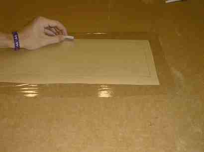
- Measure and cut the 3mm sheet of Rohacell to 30" x 7.25".
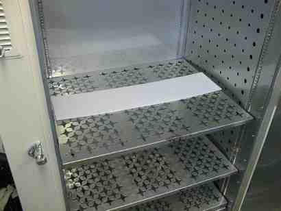
- Preheat the oven to 120°C.
- Put the sheet of Rohacell in the oven for at least 2 hours to dry it out.
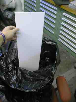
- Take the dried Rohacell out of the oven and store it in a dry environment (a plastic bag will suffice).
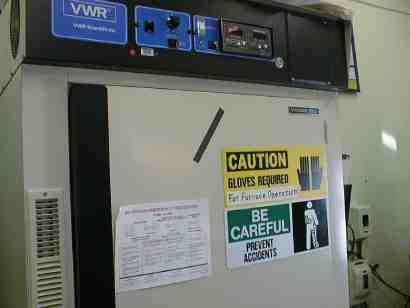
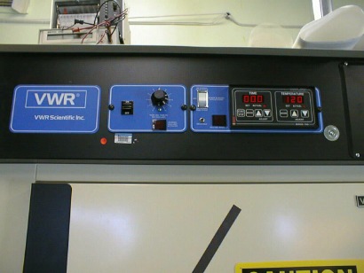
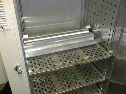
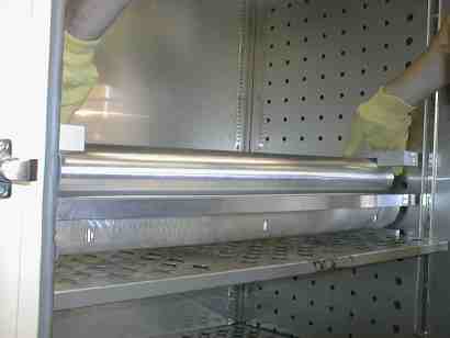
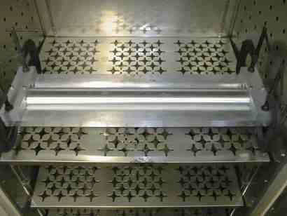
- Preheat oven and forming fixture to 185°C (If you are using the VWR 1655D oven, then set the oven temperature to 200°C, wait for the oven to warm up, put the room-temperature fixture in the oven, and in approximately 70 minutes it will have reached 185°C).
- Set the oven temperature to 185°C.
- With the fixture still in the oven, heat the dried sheet of Rohacell to 185°C (with the VWR 1655D oven at 185°C , it takes approximately 6 minutes for 3mm thick Rohacell to come up to the forming temperature from room temperature). When at the correct temperature, the Rohacell should be very pliable.
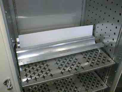
- While still in the oven, quickly put the heated Rohacell onto the bottom half of the forming fixture (the Rohacell will cool to below the forming temperature in a matter of just a few seconds).
- Form the Rohacell by assembling the forming fixture halves quickly and smoothly. When you push the top half of the fixture onto the Rohacell and into the bottom half, the Rohacell should form into a half-cylinder. Try to keep the Rohacell as centered as possible on the bottom half so that one side of the half-cylinder does not form longer than the other.
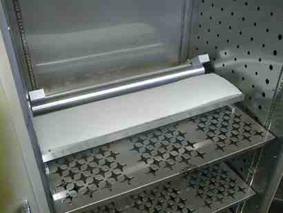
- With everything still in the oven, clamp the fixture halves together with C-clamps at the four corners to minimize the thickness growth.
- Allow the formed Rohacell to cool to below 35°C before removing it from the fixture. It is easiest to just keep the clamped fixture in the oven with it turned off.
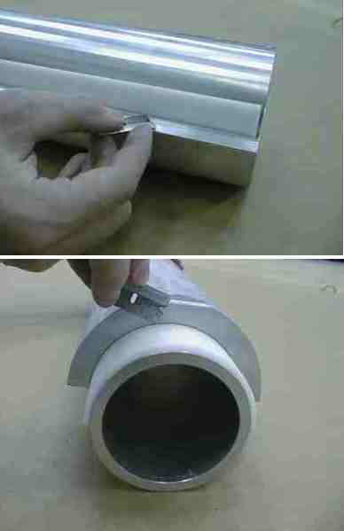
- Using the forming fixture to hold the Rohacell in place, an X-acto knife, and a measuring tape, cut the formed specimen to the final length and arc length (width) of 29.06" and 5.56", respectively. When completely disassembled, the bottom half of the forming fixture can be used as a template to cut the Rohacell to the correct arc length, and putting the whole cylinder and half cylinder of the fixture together provides a way to make the length cut square with the axis.
- Check radius and thickness values to ensure the enclosure meets tolerances using this formula:
(% Springback) / 100 * 46.5 mm + (% Thickness Growth) / 200 * 3mm < 1.68 mm
The springback can be measured by dividing the Rohacell's change in outer radius by the inner radius of the bottom half of the forming fixture. The thickness growth can be measured by dividing the change in the Rohacell's thickness from before thermoforming to after by it's before thickness.
Part II. Assembling the Inner RF Enclosure
| In order to access a completely assembled half of the MVD, the inner RF enclosure must be removed and cannot be reused. Therefore, several inner enclosures should be assembled to ensure that there are enough replacements. Once an inner enclosure is assembled it should be stored in an environmental chamber at the Phenix Hall until needed for installation, so that the uncovered hygroscopic Rohacell ends do not expand after being installed. |
Part II, A.
The Materials Needed for Assembling the Inner Radio Frequency Enclosure
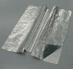
- two (2) sheets of 0.5mil thick Mylar measuring at least 30" x 35"
- one (1) sheet of 0.5mil thick Mylar measuring at least 7" x 29"
- two (2) sheets of 0.5mil thick aluminum foil measuring at least 30" x 35"
- two (2) sheets of Dielectric Polymers NT 988-2 dry transfer adhesive at least 30" x 35"
- two (2) sheets of Dielectric Polymers NT 988-2 dry transfer adhesive at least 6" x 29"
- one (1) sheet of Dielectric Polymers NT 988-2 dry transfer adhesive at least 7" x 29"
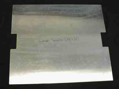
- large template (28.5" x 33") for marking cutting pattern
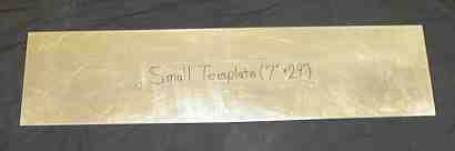
- small template (7" x 29") for marking cutting pattern
- tape (doesn't matter what kind)
- a carboard sheet measuring approximately 48" square
- a measuring tape or meter stick
- a marker
- a razor blade or X-acto knife
- a fabricated Rohacell inner cover
- a "rolling bar" at least 35" long
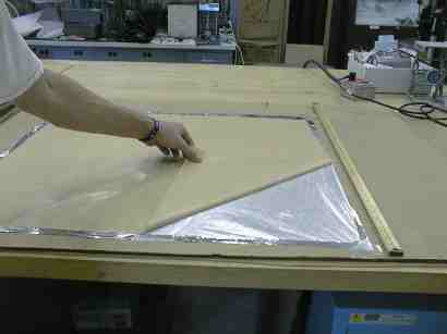
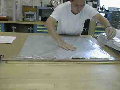
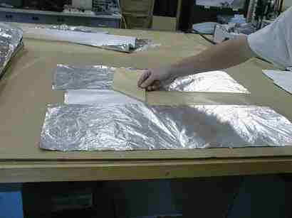
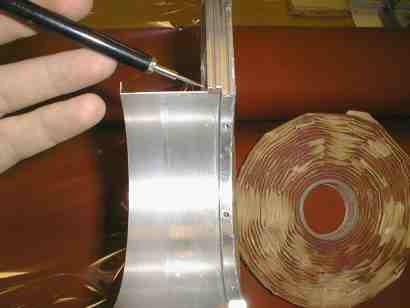
Part II, B.
The Procedure for Assembling the Inner Radio Frequency Enclosure for the MVD
- Cut out a sheet of 0.5 mil thick mylar to approximately 30" x 35" using a pair of scissors.
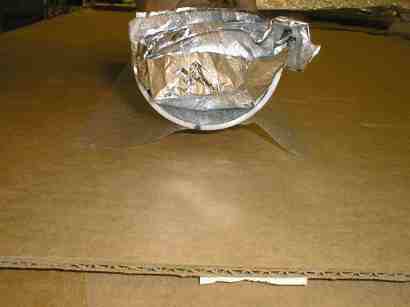
- Cut out a sheet of 0.5 mil thick aluminum foil to approximately the same dimensions with the scissors.
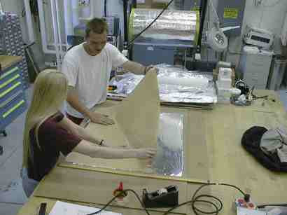
- Stretch taut and tape down the foil's corners and middles of edges onto a large, flat sheet of cardboard.
- Cut out a sheet of Dielectric Polymers NT 988-2 dry transfer adhesive to approximately the same dimensions using a sharp razor blade.
- Match up and adhere one corner of the dry adhesive to the foil and smooth out the rest of the adhesive starting at that corner while minimizing wrinkles and overlap, making sure that the adhesive is adhered only to the foil.
- Run your fingertip along the edges of the adhesive backing to ensure that the adhesive does not pull up when removing its backing.
- Slowly pull off the backing while keeping it parallel to the cardboard surface to minimize stretching of the foil.
- Restretch and retape the foil if pulling off the adhesive backing caused the aluminum foil to become loose on the cardboard.
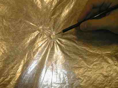
- Match up and lay down one corner of the mylar sheet on the foil/ adhesive laminate and spread it out evenly over the adhesive while minimizing wrinkles and overlap, making sure to cover all exposed dry adhesive.
- Make sure that the mylar is firmly adhered to the foil providing a very flat foil/adhesive/mylar laminate, and "pop" any large air bubbles between the mylar and adhesive with a needle.
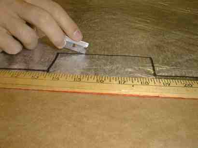
- Use a felt tip marker to mark the outline of the large template on the laminate.
- Remove the template, and use a razor blade to cut out the laminate along the marker lines. Slightly round (1/8" radius) the corners of the inner cut out portions in the middle to prevent the laminate from easily tearing.
- Repeat steps 1 through 12 to make another laminate.
- Stretch out and lightly tape down one of the cut out laminates with the FOIL SIDE UP.
- At both ends of the laminate lightly tape down a sheet of paper at the cut out section, aligning the center of the paper's edge with the center of the longer edge of the cut out section.
- Cut out another sheet of adhesive 6" x ~33".
- Match up the adhesive with the cut out portion of the middle of the laminate, and lay it down starting at one corner and smoothing out from that corner. The adhesive should overlap onto the paper.
- Run your fingertip along the edges of the backing to ensure a good stick.
- Peel off the adhesive backing starting at one corner and keeping the backing parallel to the cardboard to minimize stretching of the laminate.
- Untape and remove the papers with the extra adhesive on them.
- Lay the other laminate, MYLAR SIDE DOWN, onto the laminate with the adhesive on it. Make sure to match up the middle cut out sections precisely.
- Repeat steps 15 through 20 to lay down another layer of adhesive on top of the two laminates.
- Untape the bottom laminate from the cardboard without tearing it.
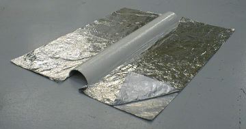
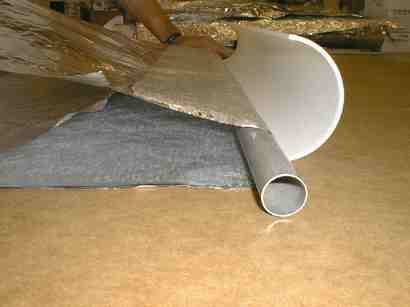
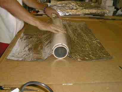
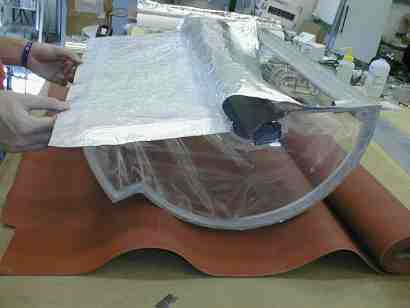
- Set up the laminates so that the middle section with the adhesive on it can be rolled onto the smaller radius side of the Rohacell inner cover with the "rolling bar". This means that the edge of the adhesive needs to be lined up precisely with the edge of the Rohacell (sticky side down and touching inside corner of
smaller radius of Rohacell), and the rolling bar needs to be placed on the opposite side of the adhesive so that as the bar is rolled towards the Rohacell, the laminates are adhered to the Rohacell at their middle sections.
- Slowly roll the laminates onto the Rohacell, and minimize the wrinkling by keeping the laminates taut at the edges.
- Firmly smooth out any wrinkles that occurred during the adhesion. This is easiest and most safely done by putting the Rohacell and laminates into the bottom half of the forming fixture, so that more pressure can be used to smooth, yet there is less chance of breaking the Rohacell.
- Stretch out and tape down the corners and edges of the 10" x
35" piece of mylar to the cardboard.
- Cut out a sheet of adhesive 9" x 34".
- Lay down the adhesive on the center of the mylar.
- Use the smaller 7" x 29" template to mark out the cutting lines on the mylar/adhesive/backing laminate.
- Remove the template and cut along the lines.
- Mark the middles of the shorter edges of the mylar with a marker.
- Mark the middles of the shorter, curved edges of the Rohacell inner cover.
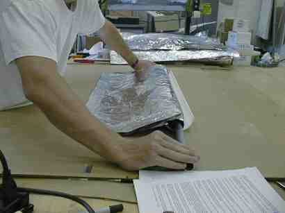
- Roll the laminates attached to the Rohacell inner cover up and push them into the "trough" of the Rohacell.
- Lay the laminate down flat with the adhesive side up, and use double-sided tape underneath the laminate to tape ONE of the long edges of the mylar to the surface.
- Align the marks for the middle of the shorter edges of the laminate with the marks for the middle of the shorter edges of the Rohacell.
- Adhere the middle edges, and then roll the Rohacell towards the long edge that is taped down, making sure to keep it taut to minimize wrinkling. The laminate will go past the Rohacell, but should not be adhered to anything yet.
- Untape the mylar from the surface and tape down the other long edge of the laminate. Then repeat the rolling process to adhere the laminate to the Rohacell.
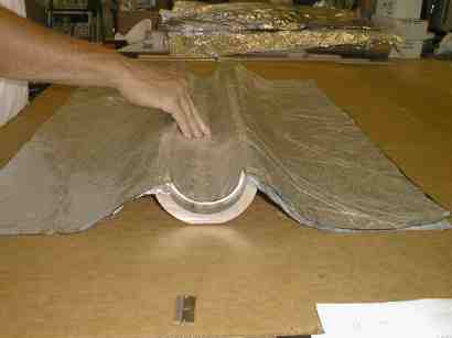
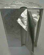
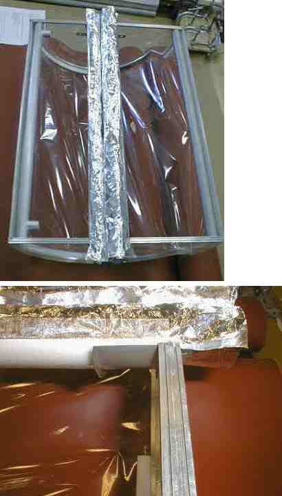
- Untape the mylar from the surface, and unroll the foil laminates from the "trough" of the Rohacell.
- Put the Rohacell down on the surface so that a "tunnel" is formed, flatten out the foil laminates on the surface, and then adhere the extra part of the mylar laminate to the foil laminate. Make sure that there is no gap between the edge of the Rohacell and the adhesion between the foil and mylar laminates.
- Press on the mylar laminate to ensure good adhesion to the Rohacell (most safely done by placing the assembly on the top half of the forming fixture so larger pressure can be applied without fear of cracking the Rohacell).
Part III.
Installing the inner RF enclosure
|
Part III, A.
The Prerequisites for Installation of the inner RF enclosure into the MVD
![]()
Part III, B.
The Materials Needed for Installing the inner RF enclosure for the MVD
- a ~40" x ~40" sheet of tacky mat material
- two ~5" O.D. half cylinders (from the bottom halves of the old and new forming fixtures)
- Two (2) inner retaining rings
- Six (6) 0.25" long, 4-40 UNC flathead screws
- Four (4) 27" long strips of 0.07 urethane O-ring material
- Eight (8) 10" long strips of 0.07 urethane O-ring material
- a flathead screwdriver
- a modified spline tool
- 1" wide double-sided tape
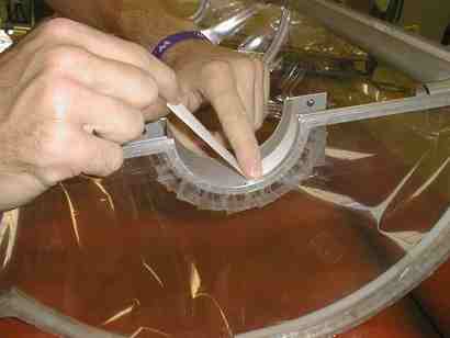
Part III, C.
The Procedure for Installing the inner RF enclosure for the MVD
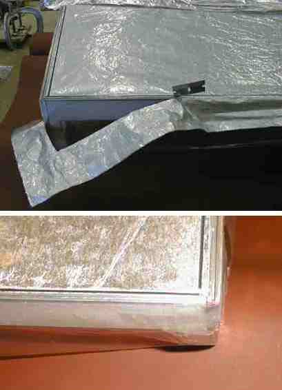
- Apply one 1" x 6" strip of double-sided tape to each of the aluminum cuffs at the edges closest to the endplates, making sure to cover the entire half circumferences of the cuffs. Cut off any excess tape. (Although the linked picture shows the mockup framework of the MVD half lying on a table, installation will actually occur while the MVD half is held securely in place by the Maintenance Test Stand.)
- Put small pieces of putty adhesive onto the corners of the inner (smaller) D-ring where the Rohacell section stops and the O-ring grooves start.
- Loosely roll the laminate flaps into the "trough" of the Rohacell section of the assembled inner RF enclosure to get them out of the way for the next step.
- Adhere the Rohacell section to the double-sided tape and putty, making sure that the edges of the Rohacell extend symmetrically to the flat edges of the D-rings where the O-ring grooves start.
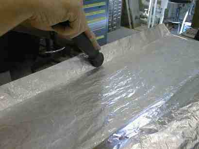
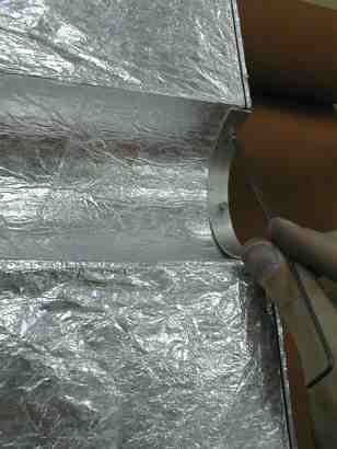
- Unroll the bottom laminate for the side closest to you from the Rohacell "trough" and pull it taut over the O-ring grooves on the side of the MVD closest to you.
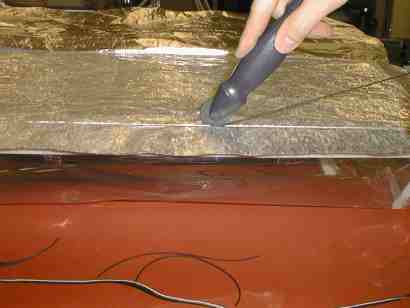
- Use the sharper disc of the spline tool to push the laminate into the O-ring groove of the longer inner seal strip of the outer enclosure. Make several light passes instead of one heavy pass so that the ripping of the foil is minimized.
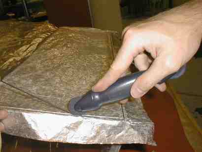
- Near one end of the seal strip, take one of the longer urethane O-rings and push it into the crease in the laminate made by the spline tool. Use one hand to make sure that the O-ring does not slip in the groove and that the MVD does not rock or tilt, and use your other hand to use the spline tool disc with the groove in its edge to push the O-ring all the way into the groove. You will have to stretch the O-ring material a little to get it to fit into the groove.
- Repeat steps 6 through 7 using the shorter O-rings for the two shorter O-ring grooves in the D-rings.
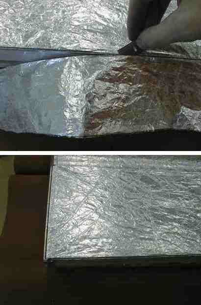
- Cut the extra laminate from around the O-ring grooves by running a razor blade along the laminate in between the inner and outer grooves.
- Repeat steps 5 through 9 on the unsealed side of the MVD half.
- Repeat steps 5 through 10 for the top laminate layer, but alternately cut the extra laminate off by running the razor blade along the outer edges of the D-rings and seal strips.
- Screw in the inner retaining rings with the six flat head screws. Check to make sure that they do not allow the Rohacell to move in the cuff and are not cutting into the laminates.