Fabricating, Assembling, and Installing
The Outer Radio Frequency Enclosure
Of the Multiplicity Vertex Detector
by Richard Conway
PHENIX-MVD-99-1, PHENIX Note 370
Table of Contents
Notes:
- All of the procedural links below reference pictures that help describe
the object or action.
- Click here to download the MS Word2.x for
Windows version of this paper (procedural pictures not included).
- Please contact Richard Conway at conway@p2hp2.lanl.gov or 505-667-1961
with questions or comments.
The MVD's Radio
Frequency Enclosure has three main parts: the inner enclosure, the outer
enclosure, and the side panels (see Figure
1 below). The outer enclosure functions as an RF shield to help insure
the required 10:1 signal-to-noise ratio is met as well as a barrier to
external temperature and water vapor to ensure that the environment inside the
MVD can be maintained. The two 0.5mil thick aluminum foil layers provide both
the approximately 8dB of RF noise attenuation at 10MHz as well as an air-tight
and water-tight seal. Rohacell IG-71 foam thermoformed to the correct
hemi-cylindrical dimensions serves as the structural support for the aluminum
foil RF shield, which is adhered to both large surfaces of the Rohacell by
Dielectric Polymer's NT 988-2 dry transfer adhesive. Two aluminum O-ring seal
strips make the electrical connections from the aluminum foil to the inner RF
enclosure. They are cemented into a small groove in each of the long edges of
the Rohacell through a conductive epoxy. The whole assembly is held in place
by two aluminum retaining rings that run along the curved outer edges of the
MVD's D-rings and by four urethane O-rings that keep the inner enclosure
locked into the seal strips.
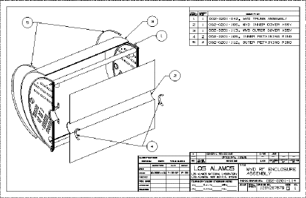
Figure 1: The MVD's Radio Frequency Enclosure
(Detail 1 is the Truss Assembly, detail 2 is the Inner Enclosure, and
detail 3 is the Outer Enclosure)
- click here for the
encapsulated postscript version
Rohacell IG-71
polymethacrylimide foam is used as the structural support for the outer RF
enclosure because of its high strength to density ratio and its long radiation
length. It is also easily machined and easily thermoformed.
Rohacell foam is
shipped from the manufacturer in 0.25" thick sheets. The sheets must be cut
to approximately the desired length and width and then thermoformed to the
correct radius using a forming fixture. The thermoforming procedure raises
the temperature of the Rohacell above its forming temperature, at which point
the chemical bonds that hold the shape of the foam break down. When the bonds
are weakened, the Rohacell's stiffness and strength are lost and itcan be
molded into and held in the desired shape by the forming fixture. When the
temperature falls back below the forming temperature, the chemical bonds
regain their strength, and the Rohacell retains the shape the forming fixture
held it in.
- VWR 1655D oven with Watlow 700 controller (or similar oven with air
circulation that heats above 185°C)
- 37.5" x 30" x 0.25" sheet of Rohacell IG-71
- thermoforming fixture (see Appendix A)
- Zetex Plus or similar heat resistant gloves
- Place the forming fixture into the oven so that the hemi-cylinder's axis
penetrates through the left and right side walls of the oven and so that the
fixture is convex when viewed from above.
- Place the sheet of Rohacell into the oven vertically so that the air can
circulate around it and heat it evenly.
- Preheat the oven to 120°C.
- Once the oven temperature has reached 120°C, let the Rohacell dry out for approximately 3 hours.
- Place the Rohacell into the forming fixture while in the oven so that it is held in the final shape desired.
- Set the oven to 185°C.
- Let the forming fixture reach 185°C (this takes approximately 45 minutes if the fixture's initial temperature is 120°C or approximately 60 minutes if the fixture was allowed to cool down while positioning the Rohacell and it's initial temperature is 100°C) and then remain at that temperature for 5 minutes. Do not let the temperature of the forming fixture or Rohacell rise above 185°C. There is no chance the fixture temperature will rise above 185°C if the oven is set at that temperature.
- Set the oven temperature to room temperature (about 23°C) and let the Rohacell and fixture cool down with the oven door closed.
- After the fixture temperature has dropped below approximately 70°C (about 3 hours), take the Rohacell out of the fixture.
- Store at room temperature and a normal humidity level until ready to machine.
The thermoformed
Rohacell must be machined to the correct dimensions before it can be
integrated into the outer RF enclosure (see Figure 2 below). Because the Rohacell has a
tendency to change shape and size during its thermoforming procedure, it
cannot be machined to the final enclosure dimensions before
thermoforming.
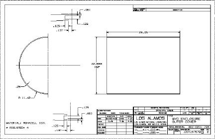
Figure 2: The Outer Enclosure's Rohacell Cover
- click here for the encapsulated postscript version
The change in
thickness due to the thermoforming process is insignificant to the
effectiveness or ability to be integrated into the final enclosure unless the
thermoforming procedure causes it to increase more than 125% of its original
thickness. The width has a tighter tolerance, because it must be held in
place by the 1/4" wide D-rings; however, the tolerances can still be met using
a sharp razor blade to cut to the correct width. The tolerance on the length
error is much tighter, because the 1/16" O-ring grooves in the seal strips
must match up with the O-ring grooves in the D-rings. Any mismatch in the
grooves could cause a tear in the airtight laminate of the inner RF enclosure.
But even this tight tolerance can be attained using a razor blade if the
Rohacell is aligned properly in the machining attachment for the thermoforming
fixture.
There is also a small groove that needs to be made in both straight edges of the thermoformed Rohacell. Each groove will provide a firm seating for two aluminum seal strips that have the O-ring grooves machined into them. The tolerance on this groove is very tight, and a milling machine must be used to achieve the amount of accuracy required. The mill must have a travel length of at least 30", and that requirement is fairly hard to meet.
- a formed 37.5" x 30" x 0.25" outer Rohacell cover
- thermoforming fixture
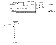
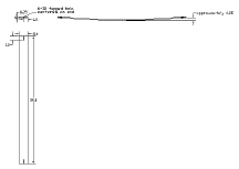
- aluminum D-rings (see Appendix B)
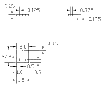
- machining fixture (see Appendix C)
- sharp knife or razor blade
- masking tape
- marker or metal scribe
- a stiff, flat object (e.g. an L-square or a parallel)
- 5/16" Allen wrench
- 1/8" diameter end mill bit
- milling machine with an x-axis travel length of at least 30" and a digital readout of the milling bed's position (Ivan Taylor, TA-53, MPF-2)
- milling bed clamps to hold machining fixture in place
** Cutting the length to specification
- Tape one of the inner seal strips to the inner D-ring and strut frame so that the O-ring grooves line up.
- Precisely mark the spot on the D-rings' edges where the seal strip no longer contacts the D-ring.
- 3a) Use the thermoforming fixture and its machining attachments to align and hold the Rohacell in place. The Rohacell should be held in place so that the flat edges parallel to the hemi-cylinder's axis can be cut. Place the Rohacell around the D-rings and mark the spots on the Rohacell where it meets the marks near the ends of the outer curves on the D-rings. Then place the large rubber sheet on the surface of the forming fixture, place the Rohacell on top of the rubber, bolt the large forming fixture attachment in place so that the marks on the Rohacell line up with the edges of the attachment, put the small rubber sheet on top of the Rohacell, and then bolt the small forming fixture attachment in place.
3b) Align the Rohacell in the machining fixture so that the marks from the D-ring alignment match up with the surfaces of the machining fixture (use a stiff, flat object to ensure that the surfaces of the bottom and top halves of the fixture are in the same plane with the Rohacell). Use themachining fixture to clamp down the straight edge of the Rohacell parallel to the hemi-cylinder's axis. Tighten the bolts on the machining fixture approximately 1/4 turn past finger tight with the 5/16" Allen wrench.
- Use a sharp knife or razor blade to cut the excess Rohacell and make the edge straight and flat.
- Loosen the machining fixture bolts, and remove the Rohacell from the machining fixture.
- Turn the Rohacell around, and repeat Steps #3 through #5.
** Cutting the width to specification
- Use the thermoforming fixture and yellow nylon straps to align and strap down the formed Rohacell, and allow one of the curved edges to hang approximately 1/4" over the circular end of the fixture. (The fixture setup is done by laying down the sheet of red rubber over the fixture surface, then laying Rohacell on the rubber, and then tightening down the yellow nylon straps around the entire fixture. The Rohacell should be aligned so that one of the flat edges parallel to the hemi-cylinder's axis is resting on the aluminum bar that extends the length of the fixture.)
- Use a sharp knife or razor blade to cut off the excess Rohacell along the curved edge.
- Measure the width of the Rohacell at several different spots along the curved edges, and make marks near the uncut edge exactly 29" from the cut edge.
- Loosen the nylon straps, align the 29" marks with the other curved edge of the thermoforming fixture, and retighten the straps.
- Cut the overhanging Rohacell off with a sharp razor blade.
- Remeasure the width at several points to ensure its uniformity.
** Milling out the seal strip grooves
- Align the bottom half of the machining fixture with the milling bed and use the bed clamps to hold it in place.
- Zero the position of the 1/8" diameter milling bit by letting it touch the front and top surfaces of the bottom half of the fixture.
- Place the Rohacell into the machining fixture and bolt it in so that the edge of the Rohacell is fulsh with the edges of the fixture halves. Use a stiff, flat object to make sure the surfaces are flush. Tighten the bolts 1/4 turn past finger tight with the Allen wrench.
- Run the milling bit down the edge of the Rohacell at Y=0.058" above the fixture's bottom surface and Z=0.132" into the Rohacell, then set Y=0.067" and run the bit back across the length of the edge. This gives a 0.134" wide by 0.132" deep groove that will allow the aluminum seal strips, conductive epoxy, and RF shielding to fit snugly together in the Rohacell's edge. Make sure that the Rohacell lips on the sides of the groove are approximately the same thickness so that the seal strips will be flush with both the inner and outer surfaces of the Rohacell.
- Loosen the bolts and remove the machined Rohacell from the fixture.
- Repeat Steps #15 through #17 on the unmachined flat edge.
Once the Rohacell has been thermoformed and machined to the correct dimensions, the assembly can begin. The assembly procedure adheres the RF shielding (aluminum foil) to the Rohacell and permanently attaches the aluminum seal strips into the grooves in the flat edges of the Rohacell as well as to the aluminum shielding.
- a partner
- formed and machined outer Rohacell cover
- two 41" x 34" 1/2mil sheets of aluminum foil at least
- two 2mil sheets of Dielectric Polymers NT 988-2 dry transfer adhesive at least 36" x 30"
- the thermoforming fixture
- the large rubber sheet used in the machining procedure
- a sharp razor blade
- a tape measure
- masking tape
- thin, clean cloth gloves (clean room gloves)
- a flat, cutting board surface (cardboard works well)
- a strip of the dry adhesive's backing at least 30" x 1/2"
- a straight-edged strip of metal 1/8" wide
- the rolling bar (a smooth cylinder at least 35" long and between 1" and 3" diameter)
- conductive epoxy
- a few cotton swabs or a small plastic spatula to spread out the epoxy
- two inner seal strips (see Appendix D)
- two outer seal strips (see Appendix D)
** Adhere the radiation shielding to the outer surface of the Rohacell
- Lay down one of the sheets of aluminum foil on the cardboard and tape the edges taut.
- With your partner's help, cut out one of the sheets of adhesive and lay it down centered and smoothed on the foil. The best way to lay the adhesive down smoothly is to adhere one corner and smooth the rest outward from that corner.
- Run your finger along the edge of the adhesive's backing to ensure that it is firmly adhered to the foil.
- Peal the backing off the adhesive. This is best done by pealing from one corner and making sure that the backing stays as parallel as possible with the cardboard, so that the aluminum foil is not stretched.
- Align one of the flat, grooved edges of the Rohacell with one of the shorter edges of the
adhesive.Place the corner edge of the Rohacell on the adhesive at least 1/2" from the adhesive's edge so that the larger radius surface of the Rohacell can be rolled onto the adhesive.
- While holding the Rohacell upright so that it does not pull on and stretch the foil, have your partner cut the masking tape from the foil around the area where the Rohacell is adhered.
- Roll the Rohacell onto the adhesive keeping the foil as taut as possible while your partner cuts the masking tape from the foil around the area you are rolling.
- Cut the excess foil from the two curved edges of the Rohacell. To avoid tearing the foil, press down on the smaller radius surface of the Rohacell and cutt through the foil at the point where the Rohacell is contacting the cardboard.
- Cut a piece of the adhesive backing into a strip that is at least 30" x 1/2" and make sure that one edge is straight.
- Have your partner hold the Rohacell upright so that the groove in the Rohacell is parallel with the cardboard.
- Align the straight edge of the backing with one of the straight edges of the Rohacell and adhere it.
- Align and lay down the 1/8" wide metal strip with the straight edge of the Rohacell and backing.
- Use a sharp razor blade to cut through the backing, adhesive, and foil along the outer edge of the metal strip.
- Remove the metal strip and peal off the backing (parallel to the foil).
- Put on the clean cloth gloves and use several passes with your fingertip to fold the foil over the Rohacell lip and into the groove.
- Use the razor blade to firmly adhere the foil to the inside surface of the groove.
- Repeat Steps #9 through #16 for the other flat edge's excess foil.
** Adhere the radiation shielding to the inner surface of the Rohacell
- Repeat Steps #1 through #4 to lay down the foil and adhesive that will be adhered onto the smaller radius surface of the Rohacell.
- Cut the masking tape off of both long sides and one of the short sides of the foil.
- Curl the shorter free foil edge around the rolling bar, but do not allow the adhesive to wrap around so much that it sticks to the underside of the foil.
- With your partner holding the Rohacell upright, use the rolling bar to adhere the foil to the corner edge of one of the grooved edges of the Rohacell at least 1/2" from the edge of the adhesive so that the foil can be rolled onto the Rohacell's surface (make sure that the foil does not get wrapped all the way around the rolling bar).
- Continue rolling the foil onto the Rohacell as your partner moves the Rohacell closer to the taped down edge of the foil. Keep the foil as taut as possible around the area where it is being rolled onto the Rohacell in order to minimize the amount of wrinkles in the shielding. Your partner can help by gently putting tension on the foil along the length of the rolling bar.
- When the Rohacell has rolled up into the foil so that the rolling bar cannot be rolled any further without tearing the foil, cut the tape off of the last edge of the foil and have your partner hold the loose edge up so that it does not adhere to the Rohacell in the wrong spot.
- Continue rolling the foil onto the Rohacell until you have rolled it past the other grooved edge. Have your partner keep the foil taut as it is rolled on by putting tension on the foil along the length of the rolling bar.
- Set up the thermoforming fixture with the large rubber sheet on top, and place the shielded Rohacell on the rubber sheet.
- Use a sharp razor blade to cut the excess foil off of the two curved edges of the Rohacell. Put pressure on the Rohacell close to the area being cut off to make a clean, straight cut (with no tearing).
- Repeat Steps #9 through #17 to adhere the shielding to the inside of the groove, but keep the Rohacell on the thermoforming fixture to cut the foil on the two straight edges to the correct 3mm width.
** Attach the seal strips
- If you are satisfied with the way the shielding rolled onto the Rohacell (satisfied with the amount of wrinkling), then mix up a small (approximately 1oz.) amount of the conductive epoxy.
- With a cotton swab, spread a very thin coat of the epoxy on the flat surfaces of the seal strips that will touch each other when assembled.
- Attach the seal strips together, clamp them, and let them dry. Make sure to wipe off any excess epoxy.
- Mix up some more of the conductive epoxy.
- Put the epoxy on the lower surfaces of the seal strips.
- Push the seal strips into the groove in the Rohacell. Start by pressing one end of the seal strip into the groove and then move down the length of the strips pushing the rest in. Be sure that the seal strip with the O-ring groove that penetrates through the side walls of the strip is nearest the axis of the hemi-cylinder with the penetrations pointing towards the axis.
- Clamp the seal strips in the correct place and let the epoxy dry. Wipe off any excess epoxy.
The integration of the Outer Enclosure with the rest of the MVD is one of the last MVD assembly steps. Only the Inner Enclosure is installed later in the process. Consequently, the integration procedure must be very safe and reliable so as to insure non-interference with the MVD electronics.
Fortunately, the integration of the Outer Enclosure with the rest of the MVD is fairly simple and straightforward. The procedure involves four steps: firmly securing the MVD to protect against bumps, seating the enclosure in the pocket formed by the MVD's aluminum frame (the D-rings and struts), aligning the O-ring grooves in the seal strips with the O-ring grooves in the D-rings, and then screwing the outer enclosure retaining rings into place.
- ten 1/4" long aluminum 4-40 flat head screws
- a small flathead screwdriver
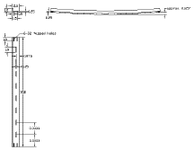
- two outer retaining rings (see Appendix E)
- an assembled Outer RF Enclosure
- the holding fixture (see Appendix F)
- Secure the MVD in the holding fixture.
- Place the assembled Outer Enclosure on top of the inner set of D-rings and in between the outer set of D-rings.
- Align one of the seal strip edges so that the O-ring grooves in the seal strips run smoothly into the O-ring grooves in the D-rings.
- Screw two flat head 4-40 screws through one of the retaining rings and into the two tapped holes in the D-ring closest to the aligned edge.
- Repeat Step #4 for the other retaining ring holes closest to the aligned edge.
- Make sure that the retaining ring makes good contact with the radiation shield. If the rings cause a little compression of the Rohacell, then good contact is insured. If the Rohacell is not held firmly in place, then put a strip(s) of indium wire in between the loose retaining ring(s) and foil and repeat Steps #3 through #5.
- Make sure that the O-ring grooves in the other seal strip edge of the Rohacell match up with their corresponding O-ring grooves in the D-rings.
- Screw in the rest of the screws starting with the ones closest to the seal strips and moving towards the middle of the Rohacell.
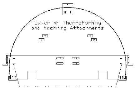
The Thermoforming Fixture and Machining Attachments Fully Assembled
- click here for the encapsulated postscript version
| 
|
| - click here for the encapsulated postscript version
| - click here for the encapsulated postscript version
|
| 
|
| - click here for the encapsulated postscript version
| - click here for the encapsulated postscript version
|
| 
|
| - click here for the encapsulated postscript version
| - click here for the encapsulated postscript version
|
| 
|
| - click here for the encapsulated postscript version
| - click here for the encapsulated postscript version
|
|
| - click here for the encapsulated postscript version
|
- click here for the encapsulated postscript version
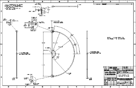
- click here for the encapsulated postscript version
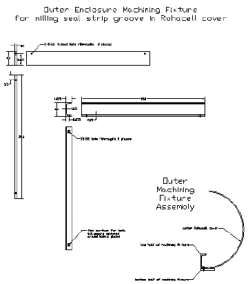
- click here for the encapsulated postscript version
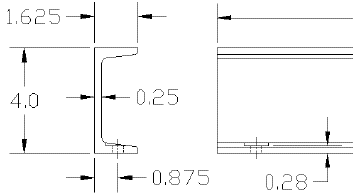
- click here for the encapsulated postscript version
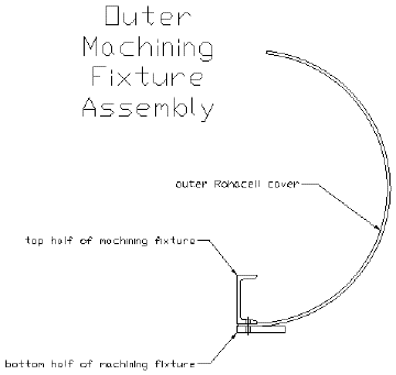
- click here for the encapsulated postscript version
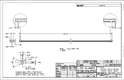
- click here for the encapsulated postscript version
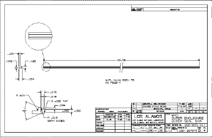
- click here for the encapsulated postscript version
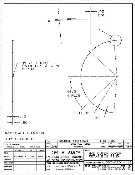
- click here for the encapsulated postscript version
Appendix F: The MVD Frame's Holding Fixture

- click here for the encapsulated
postscript version
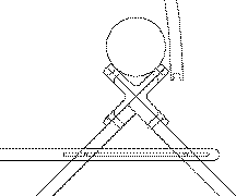
- click here for the encapsulated
postscript version
- click here for the encapsulated
postscript version


