Introduction
The MVD MCM is the basic functional block responsible for generating and
collecting all of the event data associated with the MVD subsystem. All
necessary event information is collected at the MCM from the front-end
electronics, formatted along with event and time- stamping information, and
transmitted to the Data Collection Interface Module (DCIM) for further
formatting, position stamping, and transmission to the Data Collection Module
(DCM). To facilitate adequate data transmission bandwidth using a minimized
interface, a serial port has been designed that actually consists of two
serial lines operated using a common clock. This document outlines the data
packet format, data content, and timing associated with transmitting the MCM
data using this interface.
Data Packet Contents
The contents of the data packet transmitted from the MCM are outlined in Table
1. The packet begins with the beam clock counter value that is latched when a
LVL-1 accept is issued to the MCM. This latched value provides a timing
marker in units of the beam clock for packet alignment. An event counter
follows that is incremented each LVL-1 accept and is useful for event number
alignment. The AMU cell numbers (post and pre) are then provided followed by
a data block consisting of the digitized value of all 256 channels on the MCM.
Post comes before pre due to the order of reading from the AMU for proper
correlator functioning. The final word in the packet is the column checksum.
Each bit in the checksum represents the parity of the associated bit column
of the packet. Additionally each 10-bit word has a checksum that is generated
and added as an 11-bit in the MSB position. The result is a data packet that
is a total of 262 11-bit words.
| Word # | Word Content (10-Bit Width + 1-Bit Parity) |
|---|---|
| 1 | Beam Clock Counter (Upper Word) |
| 2 | Beam Clock Counter (Lower Word) |
| 3 | Event Counter |
| 4 | AMU Cell #1 Address (Post) |
| 5 | AMU Cell #2 Address (Pre) |
| 6-261 | Digitized Data – Channels 1-256 |
| 262 | Column Checksum (Parity) |
Data Packet Format
The data words of Table 1 are transmitted using two serial data channels
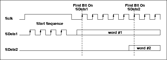
SData1 and SData2 with a common clock Sclk. Figure 1 shows the beginning of
the transmitted data packet. 4 SData1 clocks while the Sclk is high initiate
a start sequence. Following this sequence, transmission of the first word in
the data packet begins on SData1 on the next rising edge of Sclk.
Transmission of the second word in the packet begins on SData2 five Sclk
periods later. Word #3 follows word #1 on SData1 and word #4 follows word #2
on SData2 and so on until the entire contents of the packet have been
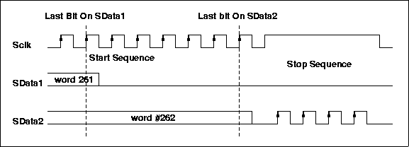
transmitted. Figure 2 shows the transmission of the ‘even’ words on SData1
and the ‘odd’ words on SData2. When all the data has been transmitted, the
stop sequence is generated by 4 SData2 clocks while Sclk is high. Figure 3
shows the end of a data packet. In general, the data lines are not allowed to
change while the Sclk is high except during the generation of a start or stop
sequence. Note that all words are transmitted MSB first, LSB last and the
MSB of each transmitted 11-bit word is the parity bit.


Packet Specifics for Correlated & Raw Transmission Modes
The MCM operates in two data collection modes: correlated and raw mode. In
correlated mode a single digitization is performed for each MCM detector
channel that represents the difference between the post and pre front-end
analog values. In raw mode, the digitized value of each of the detector
channels is transmitted as two separate data packets – the first containing
the ‘post’ AMU cell conversion results and the second containing the ‘pre’ AMU
cell conversion results. Both of the packets associated with a single event
should contain the same beam clock counter value and event counter value. The
first packet containing the ‘post’ digitized values will have the associated
AMU cell address in the AMU Cell #1 position (word 4 in Table 1) and all
‘ones’ in the AMU Cell #2 address position (word 5 in Table 1 will be 3FF ---
‘0’ parity followed by ' ‘1111111111'’). Conversely, the second packet containing
the ‘pre’ digitized values will have the digitized ‘pre’ AMU cell address in
the AMU Cell #2 position (word 5 in Table 1) and all ‘ones’ in the AMU Cell #1
position (word 4 in Table 1 will be 3FF --- ‘0’ parity followed by
'‘1111111111'’). Using this approach for both raw and correlated operational
modes allows a standard packet format and length in both instances and
provides an easy method of distinguishing between the ‘post’ and ‘pre’ data
packets in raw mode.