mechanical overview
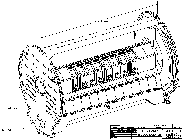
Seen here is the MVD with the outer protective shell removed. The whole device opens up along the central vertical plane; a small circular hinge can be seen at the bottom left. This is how the device is installed around the beampipe.
12 c-shaped foam cages in either half form a hexagonal barrel. Silicon panels are glued to the inside and outside surfaces of each cage, except for the central 8 cages, where the silicon is removed from the outer top face and the outer vertical face, as can be seen in the picture.
Kapton cables lead the signals down to a plenum below the barrel in which the front-end electronics are housed. From the bottom of the FEE plenum, cables can be seen carrying the signals to the endplates. On the outside of the endplates are a large number of connectors, as well as fittings for air and water cooling.
The fan-shaped segments that can be seen on the right-hand endplate are a ring of 12 silicon pad detectors.