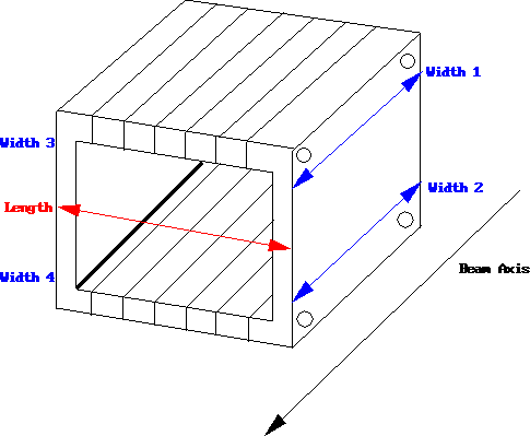
Figure 1. Shows the five measurements that were taken on the Rohacell plenum piece during testing.
PHENIX-MVD-97-34
PHENIX Note #317
1. Introduction
Rohacell C-cages were tested to see how their dimensions would change when exposed to a changing environment [1]. It was shown that silicon detectors glued to the C-cages would prevent the C-cage dimensions from changing more than the allowed tolerances. Another MVD component made of Rohacell is the central air-cooling plenum that houses the Multi-Chip Modules (MCM's). A schematic of the plenum piece is shown below. Each plenum piece can house up to 6 MCM's, one MCM for each of the 6 silicon detectors on a C-cage. There is one plenum piece for each of the 12 C-cages that make up half of the barrel for the MVD.

Figure 1. Shows the five measurements that were taken on the Rohacell plenum piece during testing.
12 plenum pieces are connected together to make up the air-cooling channel (plenum assembly) that cool the housed MCM's on one half of the MVD. The 8 central plenum pieces have only 4 functioning MCM's and the two plenum pieces on each end of the MVD have 6 functioning MCM's. To achieve smooth air flow through the plenum air-channel, foam dummy MCM's are placed in open slots inside the plenum pieces that do not require six functioning MCM's. Once the MVD is fully assembled, the 12 plenum piece assembly is held together under tension by the truss structure.
There is an assembly issue involved between the Rohacell C-cages and the Rohacell plenum pieces. The widths of the C-cages and the plenum pieces are supposed to be the same, measuring 53.2 mm. Thus, the overall lengths of the two assemblies are also supposed to be the same, measuring 638.4 mm. If the lengths of the two components are not the same, the kapton cable from each C-cage instead of being centered from the silicon to the plenum, can become twisted.
Knowing that the Rohacell C-cages are susceptible to changes in relative humidity, a similar study as that performed on the C-cages was performed on the plenum piece. Measurements were taken of the plenum's dimensions, shown in figure 1, to see how much these dimensions would change if there was a 30% drop in relative humidity in the MVD enclosure environment. This test addressed two issues: 1) if the width of the plenum pieces does not change the same amount as the width of the Rohacell C-cages, this could cause the kapton cable to become twisted and add unnecessary stress to the wire-bonds of the MCM's and the silicon detectors and 2) can the full plenum assembly contract so much as to cause the assembly to collapse?
2. Experimental Procedure
Central air-cooling Rohacell plenum pieces were fabricated by the University of California, Riverside, machine shop. Fully assembled plenum pieces were used to study assembly issues and air-cooling performance. A fully assembled plenum piece (6 Aluminum dummy MCM's installed inside the plenum piece) was used for the environmental testing.
Four width measurements which correspond to the width measurements of the Rohacell C-cage were taken. Two width measurements were taken on the top and bottom of one side of the plenum piece (widths 1 and 2 in figure 1). Two more widths measurements were taken on the top and bottom of the other side of the plenum piece (widths 3 and 4 in figure 1). One measurement in length was taken across the opening of the plenum on one side (See length measurement in figure 1).
Measurements were first taken at time zero on a plenum piece that had been stored at room ambient conditions. The plenum piece was then put into a chamber to equalize to a known relative humidity (R.H.), in this case 30%. This 30% R.H. is for BNL altitude, since the probe measures the R.H. for pressures at sea level. In order to get the LANL R.H., once must multiply by 1.28.
Measurements were taken about once a day on the dimensions until equilibrium was reached. Once at equilibrium with 30%, the plenum piece was put into a desiccator and allowed to equalize to ~0% R.H. Again, measurements were taken approximately once a day until all dimensions reached equilibrium. All measurements were taken at room temperature. A temperature/relative humidity probe was used to monitor the environmental conditions inside the desiccator and the chamber that contained the 30% R.H. air.
3. Results
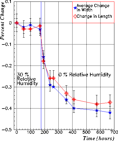
The results from the above experimental procedure are shown in figure 2. The time from 0 to 160 hours shows when the plenum piece was in the chamber at 30% relative humidity. It shows that after only about 50 hours, both the length and the width dimensions of the plenum piece had equalized with the environment. At approximately 160 hours, the plenum piece was put into a desiccator which had ~ 0% relative humidity. As one can see, both dimensions began to equalize at around 420 hours into the experiment, or approximately 240 hours after it was put into the desiccator.

Figure 2. Shows the average change in width (blue stars) and the change in length (red crosses) of the plenum piece. All error bars are statistical. The vertical line denotes when the environment was changed.
The change in width was averaged over all four width measurements. The width, shown as blue stars, changed from approximately -0.02% to approximately -0.4%, a change of about -0.38%. This corresponds to a contraction of the width of about 0.2 mm. This is consistent with the change in width for a bare C-cage that had no silicon detectors glued to it [1], but is not consistent with the change in width of a C-cage with silicon. If there was a 30% drop in relative humidity, the C-cage width would only contract by 0.08 mm, while the plenum piece would contract 0.2 mm. This means that the plenum piece would contract 0.12 mm more than the width of the C-cage.
The length measurement, shown as red crosses in figure 2, changed from approximately -0.02% to -0.36%, a change of about -0.34%. This corresponds to a contraction of the length of about 0.25 mm. This measurement though is not as critical as the width measurement.
The overall length of the Rohacell C-cage and air-cooling plenum assemblies is 638.4 mm. Taking the change in width (0.2 mm) and multiplying by 12, for the 12 plenum pieces that make up the air-cooling plenum assembly, gives an overall contraction of the air-cooling assembly of 2.4 mm. If the above situation were to occur, the length of the air-cooling channel would only decrease by to about 636.0 mm, while the length of the C-cage assembly would decrease by to about 637.4 mm. The difference between the length of the plenum assembly and the C-cage assembly would be 1.44 mm.
4. Conclusions
The above experiment was performed to see how the plenum pieces would behave in a changing environment and to determine if the width of the plenum piece would change consistently with the width of the Rohacell C-cage. If so, this would prevent the kapton cable from wanting to twist and cause stresses on the wire bonds to the MCM's and the silicon detectors.
The above experiment showed that even though the width of the plenum piece changed about the same as the width of a bare C-cage, it did not change consistently with the change of a C-cage which had silicon adhered to it. Even though the later is the case, the overall difference in the length of the C-cage assembly and the plenum assembly due to a 30% drop in relative humidity would only be 1.44 mm. Such a small difference should not cause us to be concerned with the kapton cable wanting to twist.
The above experiment also showed that even though the overall length of the plenum assembly can contract by about 2.4 mm due to a 30% drop in relative humidity, this contraction is not large enough to cause the plenum assembly to lose tension and collapse.
When the Rohacell C-cage and plenum assemblies are being assembled, it is important that the widths of a plenum piece match those of the C-cage. This would make sure that initially, the overall length of the two assemblies along the widths of the C-cages and plenum pieces will be the same, thus causing no twisting of the kapton cables.
I had a discussion Jan Boissevain, the MVD head mechanical engineer on what would happen if the plenum assembly were exposed to a high relative humidity for a long time. We discussed that since the yield strength of the the Rohacell is more than the yield strength of the endplates, if the plenum assembly were to expand, it could cause the endplates to bow just a little, but not so much as to cause concern about what kind of effects this bowing might have on the MVD.
Hubert van Hecke did a simulation [2] showing how much the Rohacell C-cage assembly could bow if the assembly were exposed to a high relative humidity over a long period of time. This bowing might increase the distance from the silicon detectors to there respective plenum pieces housing the MCM's of that particular C-cage. If the C-cage assembly were to bow, we do not believe that the bowing will be enough for us to worry about the length of the kapton cables having to take up an increase in the distance to the plenum assembly.
Lastly, if the Rohacell C-cages and plenum pieces are machined at the operating environment of the MVD and the initial matching of the widths is performed, then the maximum difference in the length of the two assemblies due to the change in the environment stated above, will only be the changes discussed above in section 3.
5. References
Eric Bosze (ebosze@p2hp2.lanl.gov)