MVD Design Review
The "Rohacell" foam used in the framework expands when exposed to moisture.
Jan Boisssevain quotes that the foam increases in length 0.22 mm over a length
of 24.6 mm when the humidity is changed from 28% RH to 78% RH. The silicon
panels do not undergo such an effect. There was, therefore, a concern that
stresses might arise from the different rates of growth between the two
materials.
Appendix 5A gives the details of a hand calculation that was done. The
calculation assumes that the foam expands linearly while the silicon is
stretched linearly. Therefore, bending of the silicon is not considered in
this calculation. A compressive stress in the foam of 96.86 g /
mm2 occurs (Maximum compressive stress is listed as 154.7 g / mm2) A
tensile stress of 219.3 g / mm2 occurs in the silicon. (Silicon
strength not available, but glass would be about 3500 g / mm2 or higher) [To
get units of PSI (lb / in2), multiply g / mm2 by 1.422]
From the results of this hand calculation, it would appear that the strength of
the foam is marginal, and the silicon is acceptable. Even this hand
calculation raises some doubt about the suitability of the foam. The FEA
analysis in the following sections shows that with bending allowed to occur, a
potentially serious condition exists.
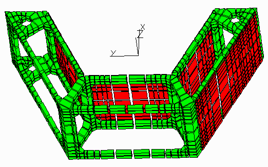
A model was made using FEA of a single C-module. The module was constrained in
the lateral directions (X, Y) about one of the holes through which the locating
plastic tubes pass. The other hole was allowed to float. The model was
restrained about its axial centerline. (Z direction) Modeling a single cell is
considered reasonable, as the forces compressing the group of cells together
are low, and therefore a single cell can grow axially without significant axial
restraint.
The 0.22 mm growth in 24.6mm corresponds to a 0.008943 mm/mm strain over a 50%
relative humidity change, or a 0.0001789 (mm/mm)/%RH coefficient of hydroscopic
expansion. This was entered into the model as a coefficient of thermal
expansion, with node temperatures being set at 50 deg temperature,
corresponding to a 50% humidity change.
The model showed quite high stresses in the area where the silicon plates are
attached to the foam. A Von Mises stress of 8,011 g / mm2 (11,392
psi) occurs on the inner surface of the middle inside plate at the inside
corners where the silicon joins with the foam. (See diagram)
Stresses in excess of 4,500 g / mm2 (6,399 psi) are typical in the model at
foam-silicon interfaces. Note that tensile strength of 71WF foam is listed as
only 323 psi. (227 g / mm2) Deflections higher than 2.0 mm (0.079 in)
also occur in the structure. A serious problem would seem to exist.
It appears that the differential expansion between the foam and the silicon is
causing a shear stress to occur where the foam is joined to the silicon. The
differential expansion also causes the foam/silicon section to bend, with the
silicon panel in the inside of the bend. This bending creating large fiber
stresses in the thin (hence, low section modulus, [ / c] ) silicon
panels. The most likely point of initial failure might be at the glue joint
between the silicon panels and the foam. As the glue would probably be
stronger than the foam, actual failure would probably be in the foam closely
adjacent to the glue joint. It is possible enough foam might remain attached
to the silicon so that the assembly might appear intact, and the panels in
place, under a cursory inspection. It might take several humidity cycles for
the effect to fully manifest itself. However, it is likely that under shock
load or other external forces the plates would easily become detached after
having been subjected to humidity changes.
The mesh used for the model of the C-module was fairly coarse, due in large
part to element count limitation necessary to model the entire module. Perhaps
most notable, but not the only instance, was that many of the 0.3 mm thick
silicon plates were extremely off-cubic in aspect ratio. (It is desirable to
have all the elements in an FEA mesh as close as practical to "Cubic" - with
height, depth and width being the same.) It was decided to model a single
silicon plate in a "window frame" of foam. A quarter section of this frame
was modeled, as it was quadra-symmetric. By concentrating on a smaller portion
of the C-module, a finer mesh would be possible without a prohibitively large
problem. The finer mesh would enable a more accurate and detailed idea of what
was happening at the silicon-foam interface.
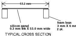
The frame approximated a section of the silicon panel that is mounted on the
outside of the C-module. In the model, the entire (not quarter section)
silicon plate measures 74 mm long by 53 mm wide and is 0.3 mm thick. The side
of the foam frame is 3 mm wide and 6 mm deep, and its 3 mm face is completely
attached to the silicon. The foam end frame is 7 mm wide by 6 mm deep, with
the silicon attached to a 1.5 mm strip on the inside edge of the 7 mm side.
The mesh is based on a 1.0 mm cube size, although some elements are off-cubic
to realize a practical model size.
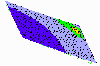
The results are shown in the diagrams following the diagrams of the C-module
model. The highest Von Mises stress is in between the silicon and foam, as
would be expected from the previous results. It is at the corner, inside of
the corner area instead of the edges of the frame. A value of 10,111 g /
mm2 (14,378 psi) is indicated. This is slightly more (26%) than the
previous value, possibly due to the more refined mesh, but not to a degree
which would indicate a major discrepancy with the C-module model. It appears
the C-module model is obtaining somewhat accurate results, and that a problem
actually exists. The stress in the foam falls off rapidly as distance from the
interface increases, and the highest stresses are concentrated very near the
interface. An upward (+Z) deflection of approximately 1.8 mm (0.10 in)
(a quite notable amount) occurs at the corner of the frame. Without the
constraints of the framework, notable and significant deflection is possible.
The expansion of the Rohacell foam due to humidity causes distortion in the
framework and high stresses in the area of the foam-silicon interface. It is
deemed that a potentially serious problem exists, with potential for
non-functioning of the assembly.
A single silicon plate in a single frame (not a C-module) of Rohacell should be
tested by exposing it to several cycles of humidity. This would test the
silicon-foam interaction while isolating any secondary effects occurring in the
C-module structure. Afterward, the foam-silicon interface should be closely
inspected for cracking or separation.
Testing of the foam on a stress-strain tester should be done to get a more
accurate idea of the foam's stress-strain curve and what the elastic limit of
the material is. Effects in both compression and tension should be measured,
as well as inelastic behavior. This would enable more realistic modeling of
the structure.
Further, more careful, testing of the foam's expansion under humidity should be
done. It appears that the curves of humidity versus expansion that were
previously done did not allow the expansion of the foam to fully stabilize and
level off at a constant value. The foam should be measured at some baseline
relative humidity representative of ambient conditions in New Mexico, probably
about 20%. It should then be exposed to some higher humidity until it has
fully stabilized, while periodically measuring the expansion. This
stabilization may take several weeks. 100% relative humidity may be easy to
obtain by saturating a small sealed container with water. It is probably
better that just one value of the higher humidity be used, rather than
ramping-up through several steps of progressively increasing humidity. Several
steps of humidity could confuse results and make postulation of a
moisture-diffusion model more difficult. Paralyene coatings, as well as other
coating, may be tried to see if they reduce total expansion reached at
equilibrium, or only decrease the rate of expansion by decreasing the
rate of water absorption.
Note that even quite slight changes of humidity theoretically result in
stresses that exceed the yield point of the foam. Unless the humidity the foam
is exposed to, during all phases of the foam's use, is controlled extremely
carefully, to a degree that is probably not practical, some distortion or
yielding of the foam in the C-module could occur. Coating the foam with
paralyene may not be an adequate solution, as the coating may not sufficiently
reduce even the short-term expansion. It is possible that the equilibrium
expansion eventually reached by the coated foam may be similar to that of
uncoated foam, only taking longer to occur.
Therefore, if it is desired to continue to use the Rohacell foam material in
the final design, it may be desirable to use some sort of hold-downs that
attach the silicon panels to the foam C-module while allowing the silicon to
move relative to the foam. An other alternative could be a significantly thick
layer of adhesive, such as RTV, that would be used to accommodate expansion
differences between the foam and silicon. Other possibilities would be blocks
of flexible material, possibly pre-cast RTV, between the silicon and foam; or
designing the foam structure so that it attaches to the silicon panels by
flexible legs or stand-offs that allow flexing to occur, constructed of foam or
other materials.
It may be desirable to consider other materials besides the foam, if it is
possible to do so, so late in the design. A major consideration is that the
density of material must be kept low so that exiting particles are not impeded.
"Density" in this case actually refers to (length)X(Relevant Particle Cross
Section), however cross section generally is somewhat proportional to
macroscopic material mass density, with some exceptions.
Carbon-epoxy laminates present a possible alternative. They offer a low
density with a high strength.
Thin, bent structures of more conventional materials like sheet aluminum may be
possible. Note that if the foam, density 0.075 g/cm3, which is 6 mm thick in
the C-module, is ratioed with aluminum, density 2.70 g/cm3, a thickness of
0.167 mm (0.0065 in.) is obtained for the aluminum, based on (mass density) X
(thickness), without cross-section considerations. Aluminum sheet 0.0065
inches thick, particularly if bent to stiffen it, might be used to construct a
credible support for the silicon panels. The aluminum-silicon junction would
have to be electrically insulated to avoid conduction between the panels.

C-MODULE MODEL, SHOWING SHUNKEN MESH

VIEW OF C-MODULE FROM INSIDE, SHOWING VON MISES STRESS, DEFLECTION X15

VIEW OF C-MODULE FROM OUTSIDE, SHOWING VON MISES STRESS, DEFLECTION X15

C-MODULE WITH SILICON PANELS REMOVED TO SHOW VON MISES STRESSES IN FOAM

TOP VIEW OF C-MODULE SHOWING DEFLECTION AND "CURLING-UP"

VON MISES STRESSES IN FINE-GRID MODEL, DISPLACEMENTS ARE UNMAGNIFIED


FINE-GRID MODEL WITH SILICON PANEL "PEELED" BACK, SHOWING MAXIMUM STRESS

Area Foam = 2 X (6mm X 3mm) = 36 mm2
Area Silicon = 0.3 mm X 53.0 mm = 15.9 mm2
From SSC SIlicon Tracking Substation, Miller et al:
Silicon E = 131.0 Gpa =

From p. 3-104 Boissevain Handout re foam properties:
71 WF Foam E = 15,435 lb/in2 =


MODEL AS TWO LINKED BEAMS:

The force of the foam in compression equals the force of the silicon in tension.


The force in the foam will be the force caused as if holding its ends rigid, less the force lost by the silicon beng stretched some distance.
Ff = (EA)f x [ (compressive strain in foam) - (tensile strain in silicon) ]

(For this case, with  ; the effect of
  could be ignored.)
From handout from Jan Boissevain:
For a relative humidity change of 28% to 78% (the conditions could be more extreme) a 0.22 mm extension of length occurs over a 24.6 mm length
Strain in foam: 


Also noting:


Stress in Foam =  (compressive) [137.7 psi]
(Compare with value in table of 220 psi.)
Stress in Silicon =  (tensile) [311.8 psi]
(Value not available, but glass typically 5000 - 7000 psi)
 / c] ) silicon
panels. The most likely point of initial failure might be at the glue joint
between the silicon panels and the foam. As the glue would probably be
stronger than the foam, actual failure would probably be in the foam closely
adjacent to the glue joint. It is possible enough foam might remain attached
to the silicon so that the assembly might appear intact, and the panels in
place, under a cursory inspection. It might take several humidity cycles for
the effect to fully manifest itself. However, it is likely that under shock
load or other external forces the plates would easily become detached after
having been subjected to humidity changes.


 ; the effect of
  could be ignored.)


 (compressive) [137.7 psi]
 (tensile) [311.8 psi]