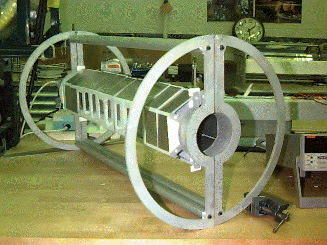
Figure 3. Photograph of the MVD support and foam prototype.
In the first assembly attempt, alignment proved difficult. Distortion
was apparently introduced in the cage support fins during the welding process.
To remedy this situation, the prototype endplates were field adjusted to achieve
two parallel planes. Also at this time, the cage span was found to be slightly
flexible. Two stiffening methods were compared, the use of paper shims and the
use of a foam spring. The spring was determined to be superior to the
shims, as it transmits a uniform force along the span. The foam spring was
adjusted empirically for a reasonable compressive force to hold the cage span
together. The weight required to compress the foam was 1 kg, which implies 10
newtons of force.
3. Test and Results
After assembly, the MVD Prototype half-shell (200 mm radius x 752 mm long)
was tested for vertical deflection or failure under increasing load. Each
endplate of the half-shell was held upright in a machine vice on a lab
workbench. A graduated scale was mounted on the workbench at the approximate
center of the cage span. Various weights were added to the center of the cage
assembly to cause sag. The deflection of the span at the
center scale was viewed
through a surveyor's transit and recorded. In this manner, three independent
tests were conducted. The assembly consisted of the items below:
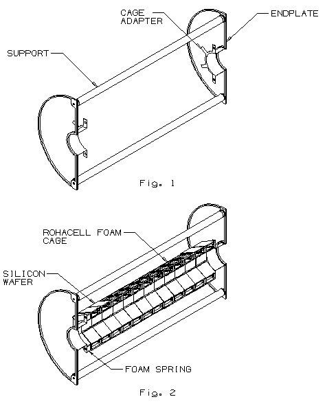
- 2 Aluminum endplates each w/ welded central silicon cage adapter (fins).
- 12 C-shape rigid foam test pieces 50.8 mm thick, 610 mm span total.
- 26 Thin straw connectors 7.2 mm diameter x 10 mm long.
- 56 Thin aluminum plates mounted in the final design pattern on foam cages.
- 2 Aluminum support struts.
- 1 Foam spring, 20 mm thick closed cell flexible foam at 10 N force.
The structure as tested had several minor deviations from the current
MVD design proposal. Rigid foam facsimile cages were designed and machined, as
finished rohacell cages were not available. Thin aluminum plates were used
instead of the silicon wafers. The aluminum plates were attached to the foam
cages using double-sided tape. For these types of tests, the most important
factor is simulating the correct mass of the components. Each rigid
foam/aluminum plate assembly was weighed and compared to an actual cage/wafer
assembly. However, the rigid foam cages at 50.8 mm were slightly thinner than
the rohacell cages at 53.2 mm.
In addition, electronic cables, having a total
distributed weight of 32.2 g, were not represented. Also, a 20 mm thick foam
spring was used to compensate for the different size cages. In the proposed
design, a foam spring with approximately 3.2 mm compressed length will be used.
4. Test Results
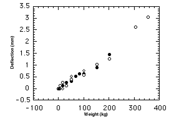
A reasonable deflection curve was produced and no failure of the system as
tested was detected. Added weights of 0 to 20 g produced
almost no vertical deflection in the
span. With a weight addition of 100 g, there was only about 0.64 mm deflection.
The assembly successfully supported the highest weight, 350 g, without failure
and displayed only a 3 mm deflection 

