Debbie Clark, Jan Boissevain, Jehanne Simon-Gillo, Jennifer
LockP-25, Los Alamos National
Laboratory
(submitted: March 9, 1995)
PHENIX-MVD-95-3
PHENIX Note #222
We built a prototype of the MVD truss structure to test the mechanical
stability, measure the deflection characteristics and review the design
concept. Our studies led to a a new design of the mounting scheme, major
changes in the endplate design and a selection of thin-walled aluminum
tubing.
We obtained models of the endplates and tubing in order to build a prototype
that resembled a Multiplicity Vertex Detector (MVD) assembly. We wanted to
measure the sagging of the structure as a whole. At the same time, because of
background considerations, we wanted to minimize the mass of the truss
structure while maintaining mechanical stability. We also wanted to minimize
any measured deflections by either modifying the design of the truss structure
and/or the mounting scheme of the MVD. We compared our deflection measurements
with calculations using standard engineering methods.
We measured the deflection of various tube sizes, both individually and within
the prototype truss structure. We chose to start with aluminum tubing to see if
the aluminum was a possible technology choice in terms of mechanical stability
and as an affordable material for prototype tests. We tested the following
tubes:
- Tube a) 25 mm diameter x 0.50 mm (0.020") wall
- Tube b) 25 mm diameter by 1.5 mm (0.060") wall
Threaded inserts
were glued into each tubing size using a 24 hour epoxy (3M Scotch Brand), and
allowed to cure for two days before the tests were started. The items were then
bolted to an immobile structure (steel I beam). Various weights were placed on
the structure and the resulting deflection was measured with a 1" gauge (0.001"
accuracy). We also measured torque-induced displacement of the assembly by
hanging weights from the outside radius of the endplate. The test set-up for
the torque and deflection tests are shown in Figure 1.
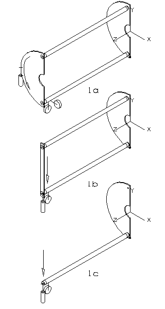
Figure 1: Part (a) shows a torque setup with a weight placed on the outside
radius of the endplate and the displacement is measured with perpendicular
gauges. (b) A deflection setup for a singele tube is shown. Deflections
measures were made for two tubes coupled with a metal stip as show in part (c).
The maximum deflection, y, was calculated and compared to lab
measurements:

where
w is the uniform load (lb/inches), l is the length (inches),
E is the modulus of elasticity, and I is the moment of
inertia.
The following measurements were taken with the test setup and proceedure
described in Section 2:
The deflection tests varied from the engineering calculations. There was an
unexplained long-term fade component; that is, the deflection measurement
increased with time. Elasticity in the glue joint is suspected to be
responsible for the fade.
We removed the inserts from the tubes and then repeated the measurements. The
measured results agree with the calculations for the tubing without the
inserts. Then we removed the initial set of inserts from the first set of tubes
and reapplied the adhesive (same brand). This time we allowed the tube/ inserts
glue joints to cure one week before repeating the original tests. The results
did improve but still contained a much-reduced fade component.
Figure 2 a and b show the results of these tests; vertical displacement is
plotted as a function of the weight applied to the structure. Both measurements
and calculation of plain tube (27" in length) as well as the measurement from
the tube with inserts (29" in length) after a one week cure time are shown in
the plot.
The tube with inserts show significantly more deflection than the tubes without
insert. The thicker-walled tubing is more mechanically stable than the
thin-walled tube.
It was found that torque-induced vibrations damp slowly on a thin-walled tube;
the thick-wall tube had a better response. We could combat any excess torque
vibrations by removing material from the outside radius of the endplates and
lightening the aluminum pieces wherever possible. The center of gravity of the
initial version of the endplate is 73.5 mm from the tube centerline; this could
be changed to approximately 50 mm. Figure 3 shows a vertical versus a
horizontal torque displacement for various weights and using a thick-wall tube.
The plot indicates the sensitivity of the truss structure to torque-induced
displacement and further supports the desire to make the endplate an open
structure.
The measured deflection of the assembly is shown in Figure 4 a & b. These
tests were performed with a metal strip attaching the tubes instead of full
endplates (as shown in figure 1) as a result of the tests described in section
3.2. The tubes include inserts which have been glued on and allowed to cure for
one week. There is no significant difference in using a thick-walled tubing
over a thin-walled tubing.
- Weld inserts rather than glue to eliminate stretch in
joints.
- With the exception of the added deflection due to the weight of
the inserts, we expect the welded tube to behave like a single tube without
inserts.
- Reduce torsion by removing outside radius material from end plates and
moving center of gravity as close as possible to the axis of the support
tubes.
- This is a major change in the design of the truss structure and
also reduces the mass of the assembly. The improved design of the truss
structure is shown in Figure 5.
- Support MVD at both ends to eliminate deflection due to
cantilever.
- This represents a major design change in the mounting
scheme. Figure 6 shows the effect of the new mounting scheme design; the
magnitude of any deflection should be reduced by a factor of ten.
- Thin-walled aluminum tubing is an acceptable material choice for the
truss structure tubing in terms of mechnical stability.
- Its effect on
background still needs to be investigated, and may not be acceptable.
Regardless, the tests indicate that a thick-walled tube is not necessary to
maintain mechanical stability, especially in lieu of the new mounting scheme
design which minimizes deflections.
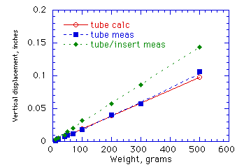
Figure 2a) Deflection for 0.020" tube.
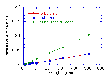
Figure 2b) Deflection measurements for 0.060" tube.

Figure 3. Torque-induced vibration test.

Figure 4. Deflection tests of double-tube truss structure
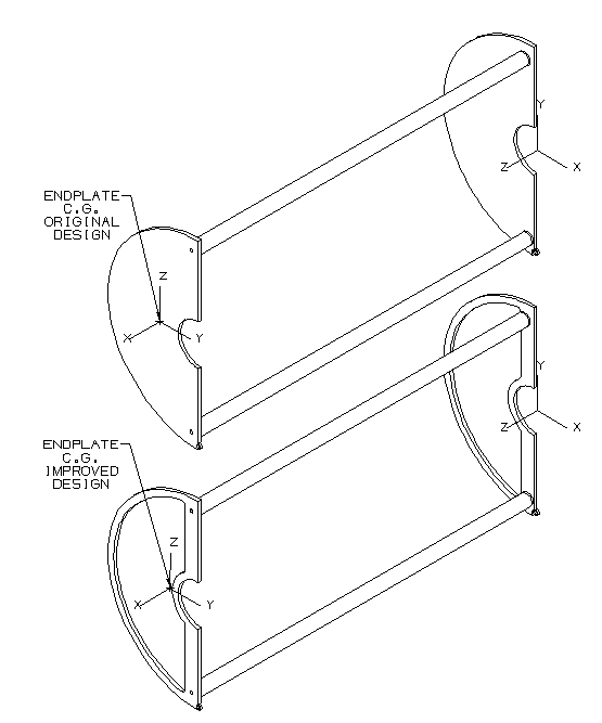
Figure 5. The conceptual design of the truss structure is shown at the top of
the figure. The improved design with the endplate as an open structure is shown
at the bottom.
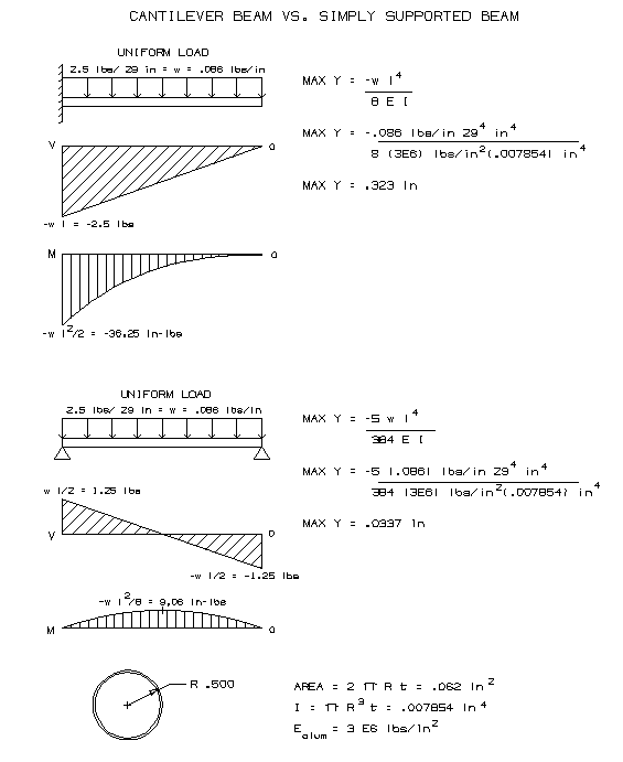
Figure 6. Demonstration of cantilever beam versus a beam supported at both ends.


