(Experiments performed from July 26 - September 5, 1995)
PHENIX-MVD-95-11
PHENIX-Note #225
 's are not converted into electron pairs
when they hit the Rohacell as this can add more background radiation into the
experiment. Because Rohacell has a low density (and consequently a long
radiation length), the photons are less likely to interact, making Rohacell a
good candidate for the silicon support structure. The coefficient of expansion
of Rohacell is also well matched to the silicon wafers.
 Rohacell is sensitive to temperature and humidity. Depending on the surrounding environment, the Rohacell will expand or contract. Therefore, the environment of the MVD detector must be controlled and stable. The design of the MVD includes a controlled environment in order to cool silicon wafers and electronics and minimize thermal stress to mechanical components. Environmental tests on Rohacell can aid in defining the specifications of the controlled environment and precautions that must be taken when handling and machining the Rohacell cages.
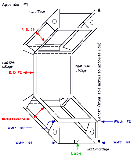
The Rohacell was machined into "C" shaped cages at the University of California at Riverside. These cages were tested at Los Alamos National Laboratory for their sensitivity to a changing environment. Radial distances and the widths of the silicon support ribs were recorded during the tests (See Appendix 1). None of the cages tested had a coating of parylene, which is being considered to add mechanical strength and to make the cages less hygroscopic (See PHENIX-MVD-95-12, "Parylene Conformal Coating for Rohacell" ).
There are specifications on how much the radial distances and widths of the cages can change. If the distance between the silicon layers in a radial line from the collision vertex changes by more than 1.7%, re-calibration is necessary to maintain pointing accuracy. The widths of the cages must be maintained to better than 0.4% to avoid mechanical interference among neighboring cages and excessive stress on the silicon-rohacell glue joint.
The purpose of these tests was to determine whether the Rohacell cages have adequate dimensional stability to meet these mechanical and physics tolerances. Rohacell cages, with and without silicon wafers glued onto them, were exposed to various relative humidities to determine at what point Rohacell fails to meet the specifications.
The second test involved three "C" shaped cages. HEXCEL glue was used to affix the silicon to the first Rohacell cage, and then the cage was cured at 60 deg.C for two hours. This is identical to the procedure used by the CDF detector at Fermilab who also used Rohacell. The cage was fully populated with silicon, three wafers on each of the inner and outer barrels. For the second cage, HEXCEL glue was used to adhere the silicon to the Rohacell , and then the cage was cured at room temperature for 24 hours, according to the manufacturer's specifications. This cage was also fully populated with six silicon wafers. The third cage contained no silicon and was used as a control for the tests. Cages 1 and 2 allow for the comparison of two differently cured glues in terms of adherence and durability.
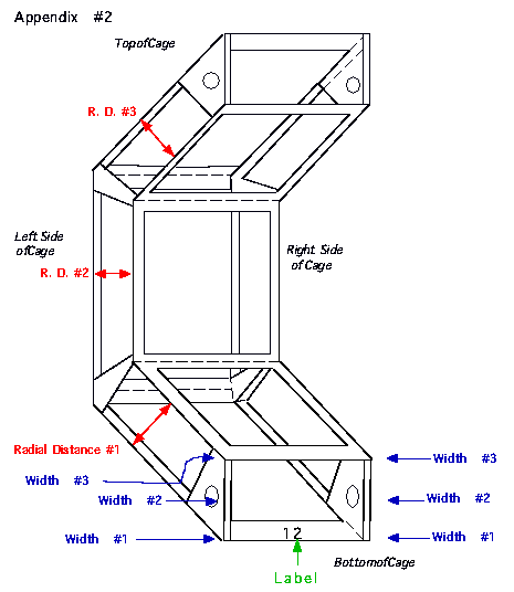
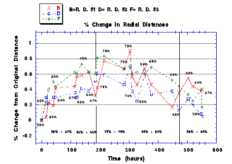
All three cages were placed in a single large glass chamber. The relative humidity was cycled from 30% to 86% and back down to 30%. In this test, three widths and three radial distances were recorded (see Appendix 2). For each test, the percent change relative to the initial dimensions at time zero were measured with a caliper to 0.001 inches. Graphs were produced showing the percent change in dimension as a function of time for various ranges of relative humidity.

Figure 1: Change in radial distances of bare cage for various humidities as a function of time.
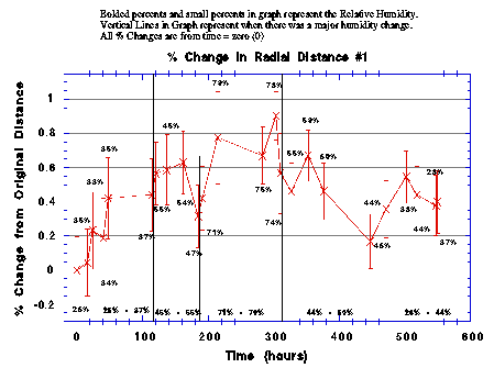
Figure 2: Change in radial distance #1 with error bars of bare cage for various humidities as a function of time.
Figure 3 shows the change in length of the cage. As the relative humidity increased, the cage began to open up or expand. The maximum change was approximately 0.55%, which translates into the cage expanding by approximately 0.9mm.
Figure 4 shows the change in width of the cage. When the relative humidity exceeded 70%, the width expanded beyond the mechanical tolerance of 0.4% . When the humidity was below 70%, the width did not expand beyond the mechanical tolerance.
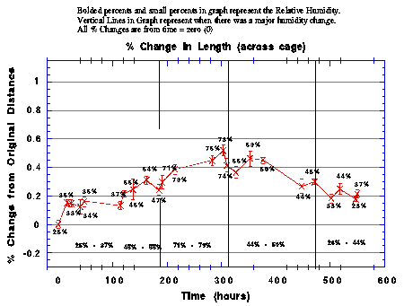
Figure 3: Change in length of bare cage for various humidities as a function of time.
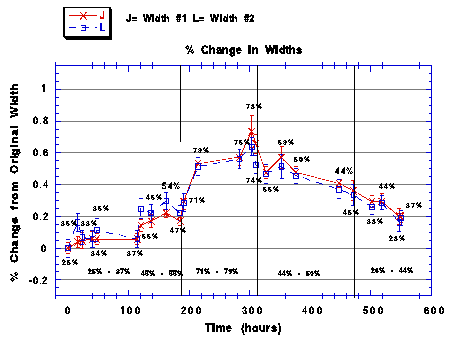
Figure 4: Change in widths of bare cage for various humidities as a function of time
The change in radial distances of the control cage reproduced the measurements from the first bare cage test. Figure 5 indicates that the radial distances did not change by more that 1%. Again, this is well below the physics limit in the radial direction.
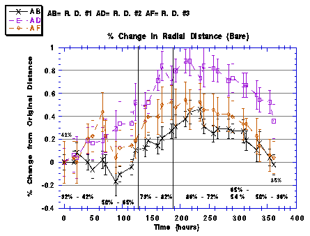
Figure 5: Change in radial distance for the bare cage.
Figure 6 shows the change in radial distance for the room temperature cured cage. There was no significant difference between the bare cage and the room temperature cured cage. Therefore, within errors, the silicon did not deter expansion in the radial dimension.
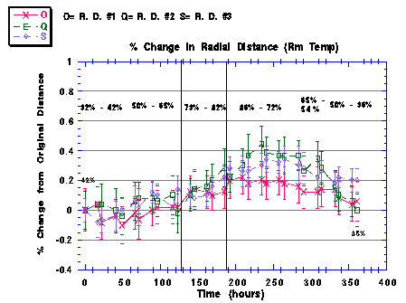
Figure 6: Change in radial distance for the room temperature cured cage.
The change in radial dimensions of the 60deg. C cured cage are shown in figure 7. Two out of the three 60deg. C cured cages behaved as the room temperature cured cages in figure 6. Similar to the room temperature cured cage, the silicon did not influence radial changes.
The change in width of the control cage is shown in figure 8. When the cage was exposed to relative humidities in the high 70's to low 80's, the widths of the cage exceeded the 0.4% mechanical tolerance. The change in width met the 0.4% limit again when the cage was exposed to a relative humidity of 65%.
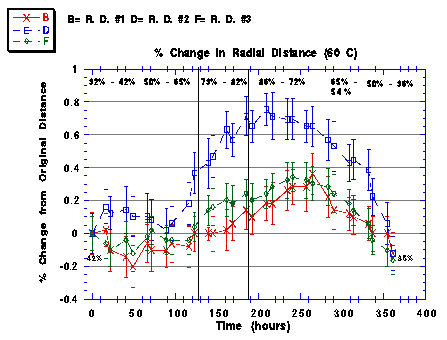
Figure 7: Change in radial distances for the 60 deg.C cured cage.
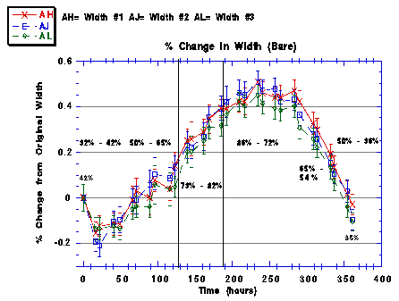
Figure 8: Change in widths for the bare cage.
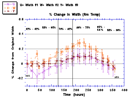
Figure 9: Change in widths for the room temperature cage.
The results from the room temperature cured cage differed from the control. In this case, the change in width did not exceed the mechanical tolerance (see Figure 9). In fact, the affixed silicon impeded the expansion approximately by a factor of two. The widths of the 60deg.C cured cage also did not exceed the 0.4% mechanical tolerance and behaved similarly as the room temperature cured cage (see Figure 10).
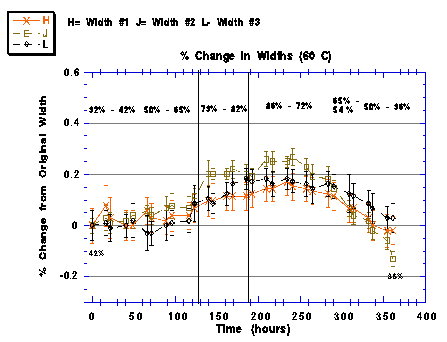
Figure 10: Change in widths for the 60 deg.C cured cage.
When the bare cage was exposed to humidities above approximately 70%, the width exceeded the mechanical tolerance of 0.4%. Figure 4 shows that if the cage was kept at a relative humidity level below 70%, then the width did not expand beyond the allowed limits. The addition of silicon deterred the change in width of the Rohacell by a factor of two. When the silicon was glued to the cages, it prevented the cages from expanding beyond the 0.4% mechanical constraint.
The measured change in length of the bare cage showed an expansion when exposed to higher relative humidities. This merits further study and comparison to a cage populated with silicon.
These results indicate that the behavior of the Rohacell in a changing environment will not be the driving force in determining the specifications of the MVD environment. If the Rohacell is kept at a relative humidity lower than 70%, then the physics and mechanical tolerances are not exceeded. In examining the figures, one also notes that the most drastic changes in dimension occur above an average relative humidity of 70%; below this limit, the changes are more modest and constant. Measurements show that we approach the mechanical limit faster than the physics limit, but do not exceed either with a fully populated cage even at high humidities (85%). It is expected that the MVD will be kept in a controlled environment at 20-40% relative humidity in order to minimize thermal stresses and effectively cool the silicon wafers and electronics. As one can see, at these low humidities, the radial distances and the widths are in no danger of exceeding their allowed limits of expansion and contraction. These tests also indicate that the environment for handling and machining the Rohacell need not be a major issue assuming the humidity is maintained below 70%. Detailed handling procedures will be defined in the near future.
We are currently testing a candidate Rohacell coating, parylene, which has been shown to decrease expansion and contraction of Rohacell in a changing environment. The addition of this coating will further loosen the restrictions on the handling of Rohacell and increase the safety margin to mechanical and physics tolerances. It is, however, recommended that the environmental tests be repeated with a partially populated "C" cage (fully populated inner barrel but only one wafer on edge of outer barrel), to verify that a cage in this scenario will not exceed the mechanical tolerances when exposed to high relative humidities. This would represent the "worst" case configuration in which we will use the Rohacell cages in the MVD and will also allow for a more detailed study of changes in length across the Rohacell cage.
