PHENIX-MVD-95-10
PHENIX Note #224
I. Introduction In preparation for a beam test in the spring of 1996, the MVD/On-line Group is designing a prototype data acquisition system to study prototype silicon detectors and electronics. This system will include all the intermediate hardware needed to pass data to CODA (CEBAF On-line Data Acquisition), part of the on-line DAQ for PHENIX test beam support. The silicon and electronics will be tested for noise, dead channels, crosstalk etc. As the silicon and electronics will not be available for several months, I have written a program to simulate the digital data from the detectors, and some analysis code combined with CODA so that we may exercise the software portion of the DAQ system before adding the hardware.
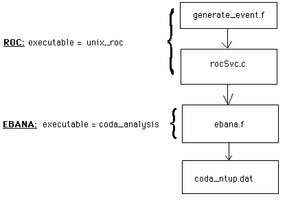
The first thing generate_event.f.jaf does is create a pedestal signal in each channel of 20 plus 2 times the return value of the internal function normgauss. Normgauss adds 12 random numbers on the interval [0, 1), subtracts 6, and thus returns gaussian values with a mean of 0 and a sigma of 1. The resultant pedestals have a mean of 20 and a sigma of 2. We chose to use gaussian distributions for simplicity since we just need to ensure that the analysis code is working properly. One of the channels is then selected at random to carry the peak, with a mean of 500 and a sigma of 20. Next, .jaf adds crosstalk to the immediate neighbors of the peak. This crosstalk is randomly determined to be between 0 and 5% of the peak signal. Below is a flow chart showing how this simulated data goes through CODA.
Figure 1: Flow chart of data through the various devices and files of CODA.
The ROC is made up by the executable unix_roc, containing (among others) the files generate_event.f and rocSvc.c (both listed in Appendix A). In rocSvc.c, when the ROC is in the "ACTIVE" state, it continuously loops and calls the subroutine generate_event, defined in generate_event.f, which creates the data array. It is then copied into another array along with some header information, and then passed to the EBANA, which is made up by the executable coda_analysis, created from ebana.f by the CODA utility codaf77 (codaf77, and ebana.f are listed in Appendix A). In the EBANA, the EB part converts the data array into a CODA standard physics event, adding more header information and copying it into yet another array which is handed to the ANA part.
The ANA section is comprised of several subroutines that I have defined to carry out the desired analysis. Subroutine usrgo executes at the beginning of a run; so here I book the Ntuple "coda Ntuple" which will store the readout data. Subroutine usrevent executes once per event. Here I do a little pre-analysis, which consists of finding the peak and it s level, and calculating the average pedestal for this event, and then add an entry to the "coda Ntuple". Subroutine usrend contains the majority of the analysis code since it executes after the run is ended and so the Ntuple is complete and we have access to all the raw data and pre-analysis results. After performing all analysis, usrend saves the Ntuple and all resultant histograms to the file coda_ntup.dat.
| IDN | HBOOK OBJECT | |
|---|---|---|
| 9 | The Ntuple created: "coda Ntuple". | |
| 98 | The "peak-counter" histogram. | |
| 99 | The "crosstalk-detector" histogram. | |
| 100 | The "pedestal sigmas, by channel" histogram. | |
| 133 | The "pedestal means, by channel" histogram. | |
| 200 | The "gain sigmas, by channel" histogram. | |
| 233 | The "signal-gain means, by channel" histogram. | |
| 101 - 132 | The "channel XX pedestals" histograms, where XX (the last two digit of the LUN) indicates the channel #. | |
| 201 - 232 | The "channel XX signal gains (adjusted)" histograms, XX defined above. |
The Ntuple is made of events containing 35 variables. The first 32 are simply the raw data from each channel; these are labeled ch1 to ch32. Variables 33 - 35 are the results of the pre-analysis performed in usrevent. 33 is the channel with the peak signal, sig_ch. 34 is the level of the peak signal, sig_levl. And 35 is the average of the pedestals for that event, ped_mean.
The main analysis is performed in 3 passes. In pass 1, the pedestal histograms (101-132) are filled. Figure 2 is an example (120). The program goes through the first 32 variables of each event checking them against sig_ch. If the current variable is not the peak, it is put into the corresponding histogram and its value added to the corresponding entry of the array chanpedmean, which keeps a running total of all the pedestals for that channel. So anything that is not the peak, is considered a pedestal; we may wish to change this algorithm in the future. If the current variable is the peak, 1 is added to the corresponding entry of the array channumhits, which keeps a total of the number of times that each channel has been hit (carried the peak). Then each entry of chanpedmean is divided by the total number of events minus the corresponding entry in channumhits, giving true averages which will be used later, as will channumhits. The mean pedestal for the run, runpedmean, is also calculated but is not presently used.
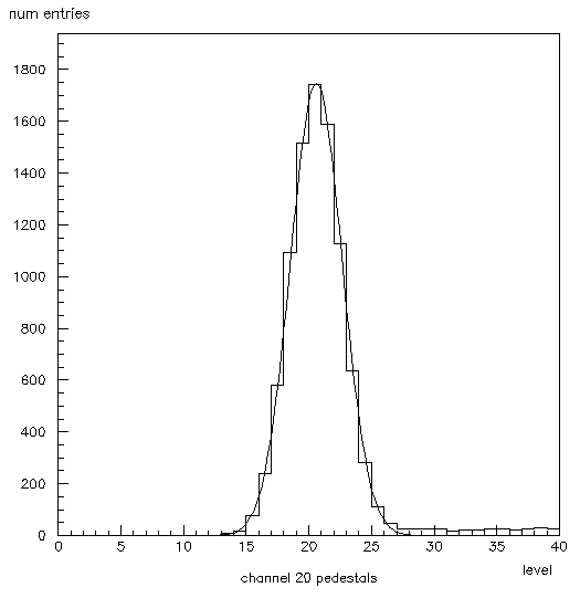
Figure 2: Histogram 120. This shows the pedestals for channel 20 fit with a gaussian. The mean is 20 and the sigma is 2. Note the crosstalk on the right side.
In pass 2, the gain histograms (201-232) are filled. Figure 3 is an example (220). The program goes through each event but only looks at sig_levl, and sig_ch. From sig_levl it subtracts the corresponding chanpedmean, determined by sig_ch. This gives an adjusted gain for that signal which is put into the proper histogram, and corresponding entry of the array changainmean, which keeps a running total of the adjusted gains. Then each entry of changainmean is divided by the corresponding entry in channumhits to give a true averages. The mean gain for the run is also calculated, rungainmean, but is not presently used.
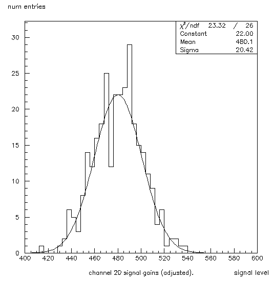
Figure 3: Histogram 220. This shows the peak signals for channel 20 fit with a gaussian.
Next the pedestal mean and gain mean histograms (133, 233) are filled. Figure 4 shows 133, and figure 5 shows 233. The program simply goes through the two arrays, chanpedmean and changainmean, and uses the index of the array, which is equal to the channel #, for the value of the bin to be filled, and fills in the contents of that entry of the array. So the x-dimension of the histogram denotes channel #, and the y-dimension denotes the mean for that channel. Remember that for the gain mean histogram (233), this is adjusted data since the mean pedestal for each channel has been subtracted from the peak signals.
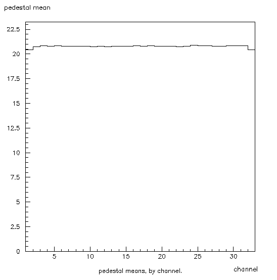
Figure 4: Histogram 133. This shows the mean pedestal for each channel. The x-axis denotes the channel number, and the y-axis denotes the mean pedestal. Note the dips in channels 1 and 32. This is due to the fact that these channels get half as much crosstalk as the rest.
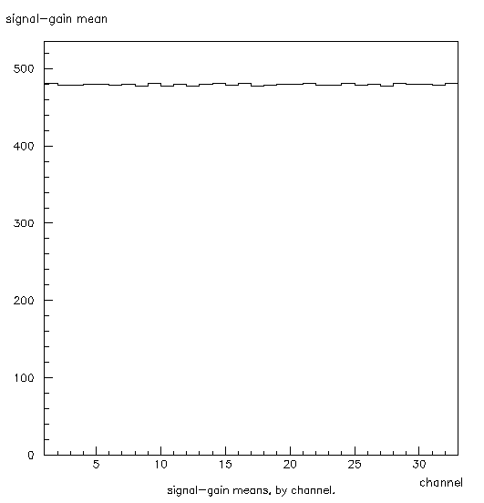
Figure 5: Histogram 233. This shows the mean gain for each channel. The x-axis denotes the channel, and the y-axis shows the mean adjusted gain. These are adjustedby subtracting the corresponding mean pedestal from the signal.
Next all the channel pedestal and gain histograms (101-132 & 201-232) are fitted with gaussian functions. The returned sigma values for each channel are stored in their corresponding entries of the arrays chanpedsigma and changainsigma. These arrays are used to create the gain sigma and pedestal sigma histograms (100, 200) in the same way as were the gain and pedestal mean histograms (133, 233). Figure 6 shows 100, and figure 7 shows 200.
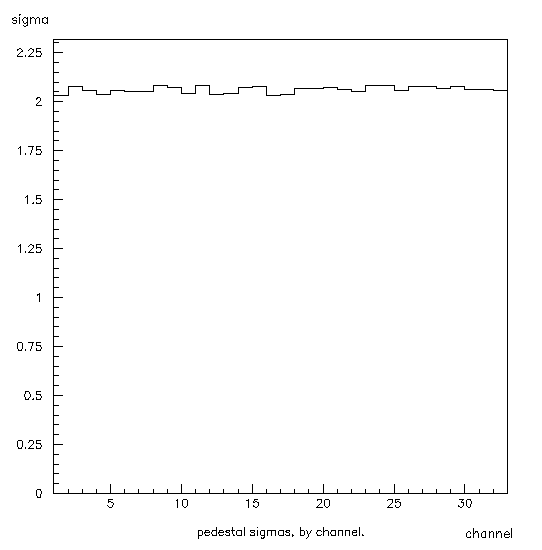
Figure 6: Histogram 100. This shows the pedestal sigmas for each channel. The x-axis shows the channel number, and the y-axis shows the pedestal sigma for that channel.
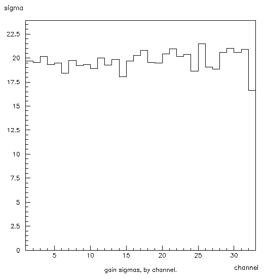
Figure 7: Histogram 200. This shows the adjusted gain sigmas for each channel. The x-axis shows the channel, and the y-axis the adjusted gain sigmas for each channel.
Pass 3 creates the crosstalk-detector and peak-counter histograms (99, 98). The peak-counter (98) is made in the same way as the sigma and mean histograms (100, 200, 133, 233) reading in the data from the array channumhits which is defined in pass 1. Figure 8 shows the peak-counter histogram (98). The crosstalk-detector (99) is a little bit more interesting. It is a 2-dimensional histogram where both axis are labeled channel. That is because it shows correlations between all the channels. The program goes through the Ntuple an event at a time and looks at sig_ch. This tells it which channel has the peak. This value becomes the x-coordinate. It then reads in the data from each channel, using the channel # as the y-axis. Thus if there were no crosstalk, this histogram would show some a high ridge on the main diagonal ((1, 1) (2, 2) (3, 3) etc.), and low fuzz everywhere else. If anything else shows up it is an indication of crosstalk. Suppose there were spikes at (10, 5) and (5, 10), this would indicate that channels 5 and 10 were influencing each other. A single spike, say at (21, 23), indicates that channel 23 is being pulled up by channel 21, but not vice versa. Making the z-axis logarithmic makes it much easier to spot significant features of this histogram. The method of plotting this histogram also significantly affects its utility. Scatter plots are useless. Lego plots work best at making crosstalk really stick out, but the main diagonal ridge tends to block large areas unless the plot is properly rotated, so it is a good idea to use a box plot as well. Figure 9 shows the lego plot of histogram 99. Figure 10 shows the box plot version.
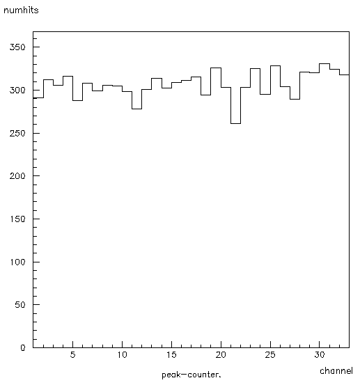
Figure 8: Histogram 98. This shows the number of times each channel carries the peak. The x-axis is the channel, and the y-axis is the number of times it has carried the peak.
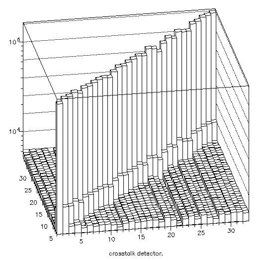
Figure 9: Histogram 99, lego plot. This is the lego plot version of the crosstalk-detector. Any spikes off of the main diagonal indicate crosstalk.
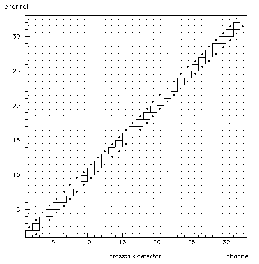
Figure 10: Histogram 99, box plot. This is the box plot version of the crosstalk-detector. Any large boxes off of the main diagonal indicate crosstalk.
All of these histograms and the Ntuple are stored in the file coda_ntup.dat. This file is over written with each run. I have also written a PAW macro to open this file, plot histograms 98, 99 (box and lego plots), 100, 120, 133, 200, 220, and 233, and then copy them into a paw metafile so that they can be printed out. The macro is "talkstuff" in the file "macros.kumac" (listed in Appendix A). The metafile created is "talkstuff.metafile", so named since I first used it to create plots for my talk at the MVD Group meeting.
To select a particular version for use, I recommend that the two versions be kept together in the same directory while retaining the .working and .test suffixes. Then you simply copy the version you wish to use to the same filename, minus the version suffix, thereby overwriting the previous version. For example:
prompt> cp ebana.f.test ebana.f Then use the proper utility to compile and link to CODA (GnuMake for rocSvc.c, and codaf77 for ebana.f). Use of these utilities is explained in Appendix A.
| File name | Location | |||
|---|---|---|---|---|
| generate_event.f.jaf | /p2hp6/usr1/jaffe/examples/unix_roc/generate_event.f.jaf | |||
| generate_event.f.kozl | /p2hp6/usr1/jaffe/examples/unix_roc/generate_event.f.kozl | |||
| rocSvc.c.working | /p2hp6/usr1/jaffe/examples/unix_roc/rocSvc.c.working | |||
| rocSvc.c.test | /p2hp6/usr1/jaffe/examples/unix_roc/rocSvc.c.test | |||
| ebana.f.working | /p2hp6/usr1/jaffe/examples/ebana.f.working | |||
| ebana.f.test | /p2hp6/usr1/jaffe/examples/ebana.f.test | |||
| macros.kumac | /p2hp6/usr1/jaffe/examples/macros.kumac | |||
| Makefile (see note 1 below) | /p2hp6/usr1/jaffe/examples/unix_roc/Makefile | |||
| codaf77 (see note 2 below) | /p2hp6/usr1/jaffe/examples/bin/codaf77 |
Note 1: Makefile is used to compile and link rocSvc.c and generate_event.f into a ROC. Makefile must be in the same directory as rocSvc.c and generate_event.f. It is used by the utility /p2hp2/usr/local/bin/make, which I call with the alias "gmake". E.g.:
prompt> gmake unix_roc
File unix_roc being the name of the executable to be created. Utility gmake must be called from the directory containing Makefile etc.
Note 2 : The utility codaf77 is used to compile and link ebana.f into an EBANA. The version above must be used since it has been modified to include and exclude certain libraries. It creates the executable coda_analysis from the following command given in the directory containing ebana.f (in this case /examples):
prompt> bin/codaf77 ebana.f
Using bin/codaf77 ensures that the proper codaf77 will be called, provided the files are left in the same directories relative to each other.