|

|

|

|

Only 6 of the 8 TGV32/discriminator positions on the PC/MCM board have a chip installed.
These tests were done when there still seemed to be an offset of one bit in the serial string. In order to test the DAC itself, the DAC values listed below are based on my understanding of this offset -- they are not what I actually setup in the pcb/mcm program. Specifically, the 5 least significant bits in the pcb/mcm program are actually the 5 most significant bits in the DAC (shift up by one bit) and the MSB in the next DAC (VMID) in the pcb/mcm program is actually the LSB of this DAC. The DAC has 6 bits.
This can be monitored at ITHRSH (pin 101) on the TGV. This DAC does not seem to give a very linear output. However, it is consistent with numbers shown in the only documentation of this DAC's performance I found. Those three points are shown as squares on this plot. Note that the square for the DAC setting = 63 falls on top of the measured data point (at 0.00V).
Although this nonlinear behavior looks bad, it is probably good and may even be by design. As shown in a study of the discriminator performance, higher values of this DAC correspond to the most sensitive (i.e. lowest) discriminator settings. So, this DAC gives us extra sensitivity for lower discriminator settings at the expense of less flexibility for higher thresholds.
Here is a plot of the DAC output voltage vs. the dac setting:
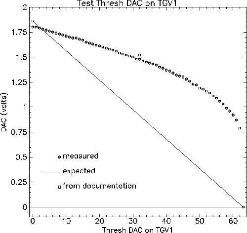
This plot is also available in postscript. The data points plotted are available here.
Here is a plot of the DAC output voltage vs. the dac setting:
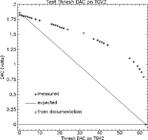
This plot is also available in postscript. The data points plotted are available here.
Here is a plot of the DAC output voltage vs. the dac setting:
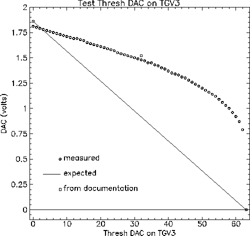
This plot is also available in postscript. The data points plotted are available here.
Here is a plot of the DAC output voltage vs. the dac setting:
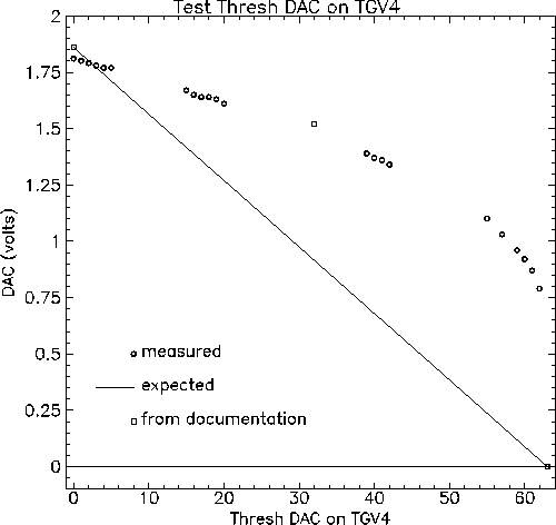
This plot is also available in postscript. The data points plotted are available here.
Here is a plot of the DAC output voltage vs. the dac setting:
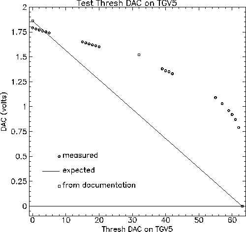
This plot is also available in postscript. The data points plotted are available here.
Here is a plot of the DAC output voltage vs. the dac setting:
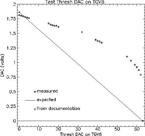
This plot is also available in postscript. The data points plotted are available here.