"). For more details on
the results of the MCM QA tests,
look here.
Because there are more global problems (bascially, they do not work
at all) on three other MCMs, I left them out of the table.
The numbers 1 -- 8 in the table below indicate AMU/ADC positions 1 -- 8.
If you look at the top of an MCM with the 256 pin input connector on your left
and the 50 pin output connector on your right, AMU/ADC number 1 is on top
counting down to AMU/ADC number 8 on the bottom.
| MCM number
| 1
| 2
| 3
| 4
| 5
| 6
| 7
| 8
| 101
| OK
| OK
| OK
| OK
| OK
| OK
| OK
| OK
| 103
| OK
| OK
| OK
| OK
| OK
| OK
| OK
| OK
| 104
| OK
| BAD
| BAD
| BAD
| BAD
| BAD
| BAD
| BAD
| 105
| OK
| OK
| OK
| OK
| BAD
| OK
| OK
| OK
| 107
| OK
| BAD
| BAD
| BAD
| BAD
| BAD
| BAD
| BAD
| 109
| OK
| BAD
| OK
| BAD
| BAD
| BAD
| BAD
| OK
| 111
| OK
| OK
| OK
| OK
| BAD
| OK
| OK
| OK
| 112
| OK
| OK
| OK
| BAD
| OK
| OK
| OK
| OK
| 113
| BAD
| BAD
| BAD
| BAD
| BAD
| BAD
| BAD
| BAD
| 114
| OK
| OK
| OK
| OK
| OK
| OK
| BAD
| BAD
| 116
| OK
| OK
| OK
| OK
| BAD
| OK
| OK
| OK
| 117
| OK
| OK
| OK
| OK
| OK
| OK
| OK
| OK
| 118
| OK
| OK
| OK
| OK
| OK
| OK
| OK
| OK
| 119
| OK
| OK
| OK
| OK
| OK
| OK
| OK
| OK
| 121
| OK
| OK
| OK
| OK
| OK
| OK
| OK
| OK
total failed
chips
| 1
| 4
| 3
| 5
| 7
| 4
| 5
| 4
| | | | | | | | | | | | | | | | |
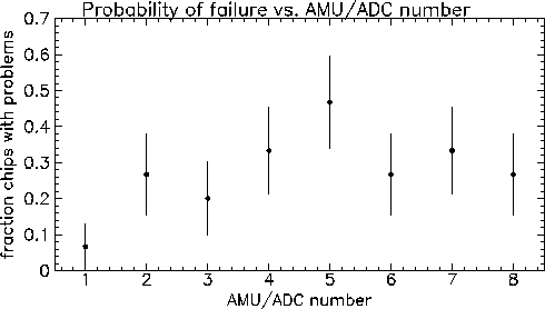
The following plot shows the fraction of failed AMU/ADC chips vs. the
position on the MCM -- taken from the data in the table above.
The error bars are statistical.

If we combine all data, as is done in the plot above, the larger
faction of failures in AMU/ADC # 5 does not seem statistically
significant. The only difference which looks (probably) statistically
significant is the lower fraction of failures in AMU/ADC # 1.
This is a source of some annoyance to us, because this is the only
AMU/ADC which has some of its signals (CLOCK_ENABLE and RAMP for the ADC)
coming to test points. So, the only chip we can do any tests on rarely
fails. In the one case the first AMU/ADC chip did fail, the CLOCK_ENABLE pulse was OK,
but the RAMP's shape was wrong.
If we look at MCM's with only one failed AMU/ADC chip, the chip
which failed is the 5th in 3/4 cases. The AMU/ADC # 4 failed in the
other case.
In most cases (4/5) with multiple failed AMU/ADCs on a single MCM,
every AMU/ADC with a number higher than the first failed AMU/ADC
also failed. I am almost certain than
most of the control "bus" lines (e.g. clock enable for the ADC)
which go from the heap manager to all 8 AMU/ADCs come
from the edge nearest AMU/ADC#1. This is because the heap manager
is on that side of the MCM.
So, a discontinuity in one of these control lines
would cause all AMU/ADCs at positions above the
break (higher numbers) to fail.
John Sullivan updated 17-Sep-1999


