Microstrip Detector to Kapton Cable Wirebond Quality Assurance Procedure.
Mike Bennett, David Jaffe, Toshiyuki Shiina
Los Alamos National Laboratory
PHENIX-MVD-99-XX
I. Introduction
This note documents the procedures, equipment, and specifications used in testing the wirebond connections between the silicon microstrip detectors and their kapton cables. Given that the double-metal pad detectors are wirebonded directly to their Multi-Chip Modules, it is likely that a separate procedure and setup will be required for their testing.
II. The Test
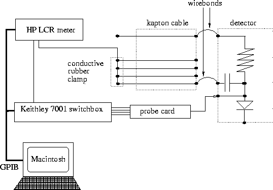
The measurement made to test the integrity of wirebonds is the capacitance between the readout traces and P implants of the detector. The P implants are contacted via the spy pads using the 32 pin, 200-micron pitch probe card. The readout traces are wirebonded to the kapton cable, and are contacted through a conductive rubber clamp that shorts all the readout traces together. See figure 1 below for a schematic diagram. The Keithley 7002 switching mainframe is used to select one of the 32 pins to connect to the HP 4784A Precision LCR meter. The capacitance is then measured between the selected channel and the shorted readout traces. This measurement process is performed in a dark box as it is sensitive to incident light, and is automated by a LabVIEW Virtual Instrument "wirebond test.vi".

Figure 1: Schematic diagram of the measurement setup.
[test procedure]
III. Interpreting the Results
Due to the geometry of the assembly, the dominant capacitance in the setup is that between a readout trace and its correspond
Micron Semiconductor, as a part of their standard in-house QA, test all strips for shorts between the P-implant and the readout strip. A shorted strip will show up with a capacitance similar to that of a broken wirebond, i.e. ~50 pF. If a confirmed measurement shows a capacitance in this range, one must consult the Micron data for that particular detector before concluding that it results from a broken wirebond. The Micron data can be found in the white three ring binders that contain our silicon detector test data. Other strips which show a confirmed capacitance of between 100 and 400 pF are considered as minor fault in the detector itself and are not severe enough to be counted as shorts.