Kapton Cable Quality Assurance Procedure
Toshiyuki Shiina
The University of Alabama in Huntsville
September 22, 1999
- Introduction
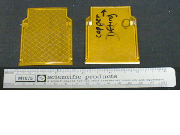
This note documents the procedures, equipment, and specifications
used in testing the kapton cables. The kapton cable is used in the MVD
to connect the 256 readout traces of the silicon strip detector to the MCM
and to supply bias voltage to the detector from the MCM. The kapton cable
consists of five layers of materials as follows:
- kapton cover lay,
- copper shielding grid and bias pad,
- kapton base,
- gold plated copper traces and bias lines, and
- kapton cover lay.

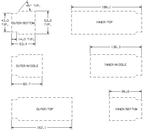
We use 6 different kinds of kapton cables for 6 geometries of silicon strip
detectors as shown below.

Testing
[Setup and Procedure]
The cables received from ALLFLEX are clearly labeled, e.g. POM-01 (Production
kapton cable Outer/Middle number 01). Then the visual inspection is conducted first.
The cable is placed between glass plates under the microscope. It takes about 5-10
minutes to scan the trace side of the cable depending on the surface area.
Cables that have discontinuities in the trace, inter-trace shorts, and/or very thin
traces (trace width < 50% of nominal trace width) are marked as bad. At this stage a quick bias line continuity test is conducted with a handheld
multimeter. The bias lines run on one side of the cable and go to the bias pads on
the other side through via holes. Electrical continuity between the bias lines and
the bias pads is tested by measuring the resistance between the former and the latter.
Only kapton cables which pass the visual inspection and the bias line continuity test
should proceed to the electrical QA test.
Setup
The second step is the electrical tests to ensure the visual inspection result.
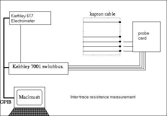
Two types of electrical tests are conducted. One is a measurement of inter-trace
resistance to find inter-trace shorts. The inter-trace resistance should measure
larger than 100 MOhms to ensure no cross signals between channels. The other is a
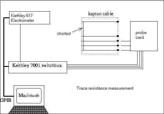
measurement of resistance of two adjacent traces to find discontinuities in the traces.
(Two traces are shorted together, and the resistance between two bonding pads are
measured.) The 32 pin 200 micron pitch probes touch the bonding pads on the silicon end
of the cable. LabView controlled switch box selects two adjacent traces, and the
electrometer measures the resistance between them. In the inter-trace resistance
measurement the circuit should be open and the resistance should measure infinity.
In the trace resistance measurement the circuit should be closed through the shorting bar
on the bonding pads on the MCM end of the cable and yield less than 10 Ohms. (The wiring
has internal resistance of ~5 Ohms and cannot be eliminated.)
The kapton cable resistance measurement scheme is shown below.


Procedure
- Set the cable on the aluminum jig with a teflon bed (see below).

- Place the shorting bar over the bonding pads on the MCM end of the cable. (For
trace resistance measurement ONLY)
- Run "kapton testing.vi" (LabView virtual instrument program)
- Store the resistance data file in the directory "kapton data" on the PC.
- Run the PC program called "neatkap.exe" to make a table containing channel number,
inter-trace resistance, and trace resistance.
- Print out the table and file the hard copy in the 3-ring binder note labeled
"kapton testing data."
Result
If one finds low inter-trace resistance (suspect for shorts) or high trace resistance
(suspect for discontinuity) that was not found in the visual inspection stage, the cable
should be re-inspected under the microscope to locate the defects. A trained tester's
eye can detect >95% of the defects visually, and the rest should be caught electrically,
which is reconfirmed visually to ensure a 100% confidence in the cable's performance.
All the inspection result is available in the form of hard-copies in the 3-ring binder note
labeled "kapton testing data" and in the form of ASCII file table on the CD_ROM labeled
"kapton testing data."
Appendix - Links to the final kapton cable inventory list
1. Inner/Bottom kapton cable data sheet
2. Inner/Middle kapton cable data sheet
3. Inner/Top kapton cable data sheet
4. Outer/Bottom kapton cable data sheet
5. Outer/Middle kapton cable data sheet
6. Outer/Top kapton cable data sheet


