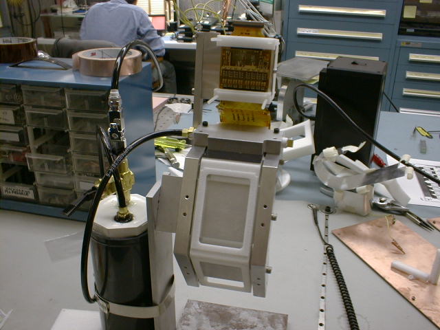
| Rear view of attachment of first face (outside bottom) of the first production C-cage. As seen here, the cage is mounted on the C-cage gluing fixture. The Si strip detector is being held on the cage with a vacuum fixture, and the MCM can be seen at the very top where the MCM plenum is constructed. | 
|
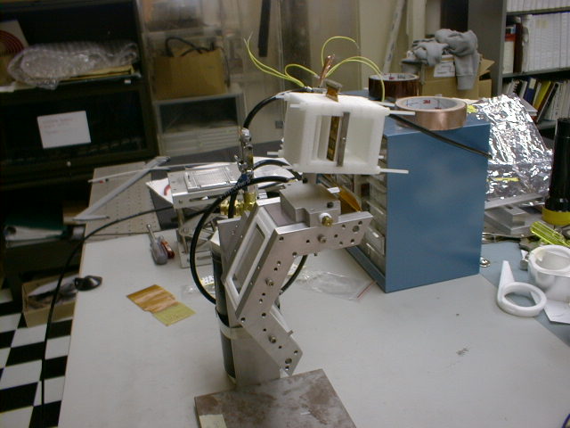
| Side view of attachment of first face (outside bottom) of the first production C-cage. | 
|
| Endplate assembly. The aluminum pieces are alidited to improve electrical contact, and then 4 separate pieces are glued together with conductive epoxy to make the assembly seen here. | 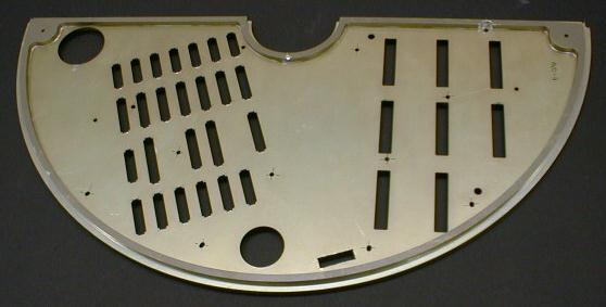
|
| Full endplate stack assembly (except for C-cage stack), sitting on top of the stacking support jig. This includes, from the bottom, endplate, motherboard, pad detector rohacell plenum (with one pad detector inserted), daughter card for reading out pad MCM's, and some rohacell pieces for directing cooling air. Just inside of the pad detector is the aluminum cuff which supports the C-cage stack. Except for the pad detector, this is an actual assembly with production pieces. | 
|
| Sample of 3 prototype cages, put together in a stack. These contain Si which has failed QA tests, real kapton cables and G-10 mechanical "dummy" MCM's. One of the cages is fully populated (all 6 faces) and the other two are partially populated (all inside faces plus outer bottom). Used to develop gluing and stacking procedures | 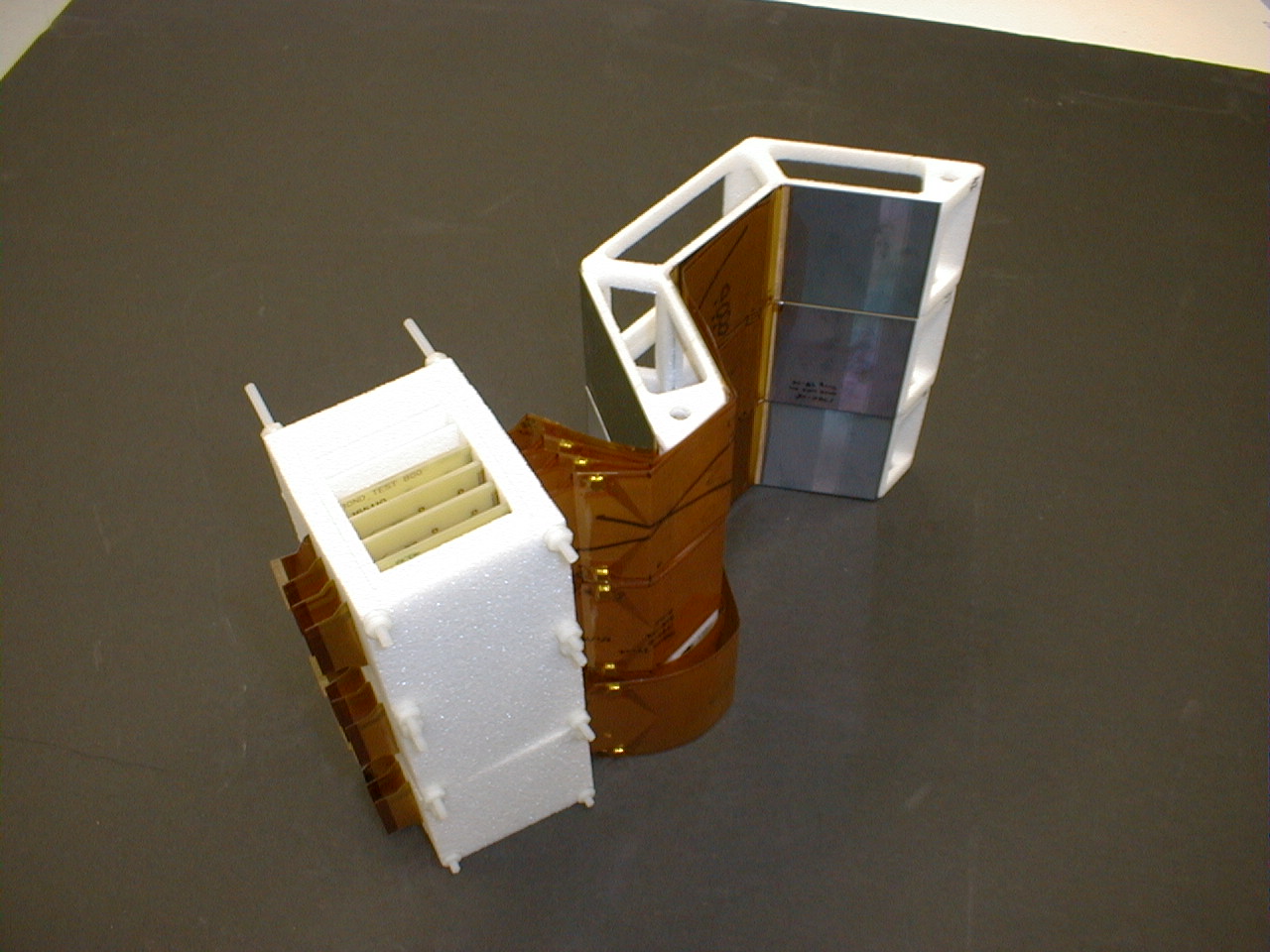
|
| Six cage stack, inside stacking jig. The bottom three cages are the mechanical prototypes described above, and three are empty to fill the stack (A six cage stack comprises 1/4 of the MVD). On top of the cages and the MCM plenum (white vertical column on the left) are calibrated pressure plates, exerting 3 newton (cages) and 10 newton (plena) forces on the stacks, simulating the compressive forces in the fully constructed MVD. On the far left is a power-communication board attached to MCM output cables. | 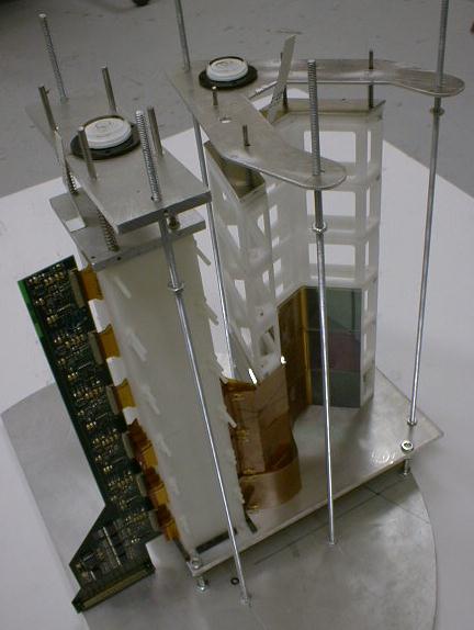
|
| 6-cage stack with all 6 power-communication boards, attached to the endplate stack. The metal pieces around the bottom of the power-communication boards is a fixture for inserting the boards into their connectors. The merging of the two stacks requires the simultaneous connecting of all 6 power-communication boards to their connectors on the motherboards, the insertion of the plenum stack into a collar in the cooling air path (with proper vertical shimming) and the attachment of the lowest C-cage to its support cuff, using straws and vertical shims. This assembly represents 1/4 of the MVD. | 
|
| 1/4 MVD assembly, rear view, with power-communication board insertion jig removed. The sample pad detector can be seen from this view. | 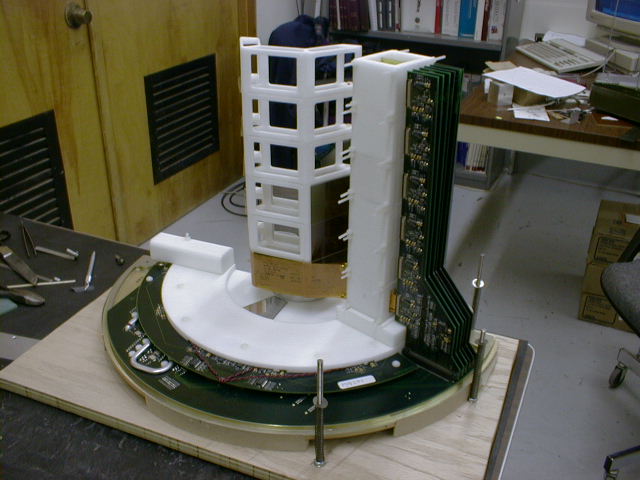
|
| 1/4 MVD assembly, front view. | 
|
| 1/4 MVD assembly, front view, with an outer RF enclosure set in place around the outside of the endplate. | 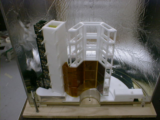
|
| Gluing of the first production pad detector-MCM assembly, inside gluing jig. This picture shows the pressure cure of the pad detector to the G-10 bridge which holds the MCM. | 
|
| Area for the chain test. Rack on the left contains the DCM, DCIM, and is read out by MiniDaq. The C-cage is inside a lighttight container (the black box on the right hand side of the photo | 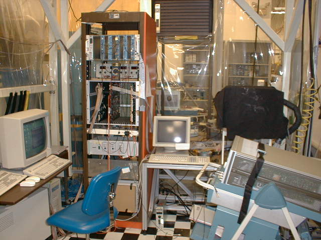
|
| Chain test area from a different view. This view shows the motherboard with input power and output signal cable connections. Also shown is the input hose for cooling air. | 
|
| View of C-cage in "lighttight box" in chain test stand. The cage is held on a gluing fixture, with one of the spacer blocks removed to allow the use of a source on the silicon. The source and trigger scintilator can be seen in this view. In the rear, the plenum can be seen, where the MCM is plugged into a power-communication board. | 
|