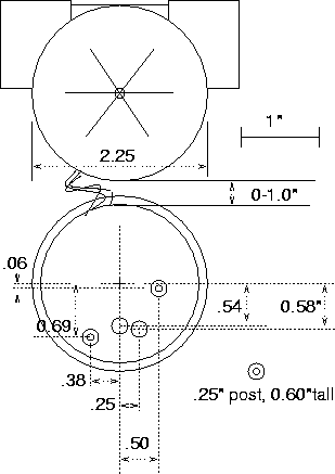
The postscript file prints out on a 1:1 scale (at least on the printer in 218). To make sure, there is a 1" scale marker. You can use the ps printout as a template to drill the 2 post holes (0.15" diam) and the 2 LED/setscrew holes(0.2" diam).
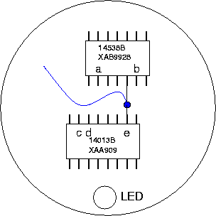
 On the PC board I tried to locate a point that would deliver an analog signal.
Point a and b go down from 8.4V to 2.9V as flow speed goes up from 0. Point e
goes from 0V to 5.8V as flow speed goes up. Points c and d switches in concert
with the LED going on/off.
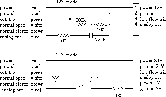
The signal on point e is a square wave with 5ms top, and a low which varies from 2-30ms and more. If you integrate this, you get a DC voltage proportional to the flow speed.
