The primary physics goals of the PHENIX Muon Detectors are to contribute to both the Relativistic Heavy Ion Program and to the Spin physics program in the PHENIX experiment. The physics requirements have led the muon subsystem to choose as the baseline detectors for the muon spectrometers the cathode strip chamber (CSC) technology. The PHENIX muon spectrometers are radial field magnets with 3 detector stations along the axial length of the magnet at locations of 2 m, 3.5 m, and 6 m. Because of the need to maintain good momentum resolution down to 1.5 GeV, the second detector station had to have as small a radiation length as possible. We have successfully constructed a full size station 2 chamber with a radiation length of 8.5 x 10**-4 by using thin 25 micron metalized mylar foil with the metalization electroetched in the form of straight 5 mm strips and 5 mm radial strips. The station 2 chambers are octants with an expected resolution of less than 100 microns.
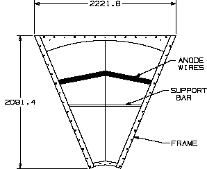
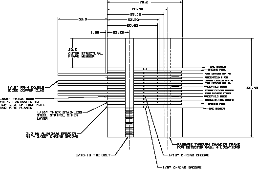
The station 2 chambers are shown in Figures 1 and 2. Each octant consists of three individual CSC detectors with a cathode to cathode gap of 6.5 mm. All cathode planes and all anode planes are read out to give three separate coordinates, r, phi, and stereo for each detector that allows for ghost hit rejection at the detector level. Each cathode and anode frame consists of laminated aluminum and epoxy fiberglass layers for a thickness of 3.25 mm. The 9 total layers of cathodes and anodes are sandwiched between two 3.2 cm thick by 7.5 cm wide aluminum structural frames that provide rigidity to the individual frames, maintain the tension of the anode wires and cathode foils, and determine the absolute location of the cathode strips by 9 precision alignment pins.
The full scale station 2 prototype consists of two CSC detectors with anode wires and one etched cathode for each detector for a total of two anode planes and two cathode strip planes and two cathode ground planes. The cathode strip planes were etched with a specially fabricated 3 m x 3 m precision xy table on which a 3 m optically encoded leadscrew was mounted that held the electroetcher assembly. The 25 microns alignment accuracy of the xy table in x and y for etching the cathode foils was accomplished by an autocollimator mounted on the leadscrew. The electroetcher is a tungsten pen that is held at -16 volts with respect to the foil. To etch a line the pen is lowered to the foil with approximately 5 grams of force on the foil and then moved by the lead screw. One half of the octant foil was etched with straight strips parallel to the center of the octant 5 mm wide and the other half of the octant foil was etched with radial strips 5 mm wide at the outer radius. The readout of the cathode foils utilizes the floating strip method in which every other strip is floating. The readout is at 1 cm intervals. The anode planes consist of alternating sense and field wires on a 5 mm pitch. To minimize resolution degradation due to entrance angle, the anode wires are supported at 22.5 degrees at the center of the chamber and "kinked" so that the wires follow the chord on either side of the support. The anode support is 5 mm wide plastic with machined grooves fastened to the outer frame and allowed to float in the inner frame.
A full structural static analysis of the chambers has been performed to understand the distortions that will occur due to gravity, thermal and magnetic effects. A dynamic analysis was also performed to understand the distortions due to environmental noise. We have found that the maximum distortions due to gravitation is 0.362 mm with thermal and magnetic distortions much less. Dynamic distortions due to vibrations from the environment (pumps, compressors, etc) are less than 1 micron. An active alignment system will be used to correct for the static distortions.
We will discuss the results of the mechanical and electrical tests as well as the resolution. The stability will be described as well as the mounting system in the magnet.

