M. L. Brooks, D. M. Lee, W. E. SondheimLos
Alamos National Laboratory
The PHENIX muon tracking system will be used to reconstruct upsilon vector
mesons with a mass resolution of 200 MeV/c2. To achieve this mass resolution,
we must have a spectrometer momentum resolution of better than 2% at the
momentum of upsilon decay muons which is typically 10-30 GeV/c. With three
tracking stations and three fine resolution chambers at each station, we
require a chamber resolution of 100  m to obtain this momentum resolution. This corresponds to a station
resolution of 58
  m. In order to
make sure that the alignment of the chambers to each other does not contribute
significantly to the momentum resolution, we would like to measure the relative
alignment of the chambers to each other to 25
  m or better over a distance of 4 meters.
Achieving this type of alignment measurement precision is a multi-step process
which involves accurately etching the strips of the cathode strip chamber
relative to the chamber frame, accurately placing alignment measuring
components onto the chambers with respect to these strips, and then having an
active alignment measurement which measures relative alignments to better than
25  m.
m.
We have used an autocollimation technique with precision balls on the external
chamber frame to achieve the accurate etching of the strips relative to the
chamber frame, and plan to use a system of optical fibers, lenses and
photo-sensors to measure the alignment. The autocollimation system that we are
using, which is attached to our etching apparatus, is capable of determining
the positions of precision balls to an accuracy of 5  m. The precision balls that we are using rest on top of
precision alignment pins which hold the alignment of our chamber frames. We
then measure the positions of these pins to establish the orientation of the
etching apparatus with respect to the chamber frame. The measurement of the
entire chamber frame with respect to the etching apparatus has been found to be
limited by the accuracy of our alignment holes and pins and the accuracy of the
lead screws which move the etching pen and autocollimator. We have found that
the system is capable of determining the chamber coordinate system with
residuals of 25-50
  m, which is
equivalent to the errors in the alignment pins and lead screws of our prototype
system. Work that will be done to improve the system will also be presented.
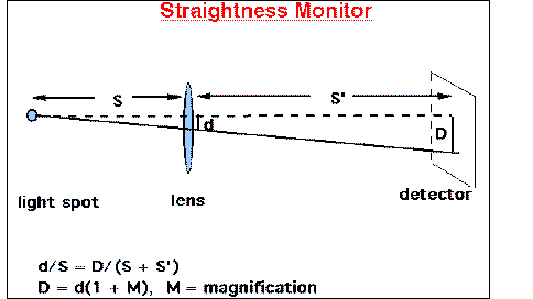
An overview of the light source-lens-detector systems that will be used to
measure the relative alignment of the chambers at the three stations will also
be given (see Figure 1). Several different photo-sensors and light sources
have been tried and the comparison of them will be shown, with the expected
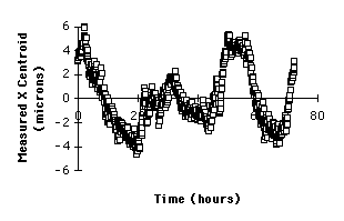
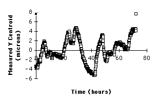
measurement precision of the final chosen system. The systems have typically
been found to be capable of measuring the alignments to +/-5  m, with no special thermal or
background light controls (see Figure 2 where the position measurement of a
light spot on a CCD camera is shown over the course of a weekend).
The required placement precision of the alignment components on the chambers
has also been studied, including angular tilts of the different components.
The translational requirements are obviously equivalent to our measurement
requirements. The angular position of the lens must be accurate to
approximately 1 because refraction of the light through a tilted lens
causes a displacement of the light spot. Finally, a description of the mounts
that will achieve our required precisions will be given.

Figure 1: Schematic of straightness monitors which will be used to measure the
relative alignment of the three muon stations with respect to each other. The
light sources will be located on station 1 chambers, the lenses will be on
station 2 chambers, and the light detectors will be on station 3 chambers.


Figure 2: The measured x and y positions of a light spot over the course of a
weekend. The light source, lens, and detector were in the same spacing as they
will be in the muon system.
 m to obtain this momentum resolution. This corresponds to a station
resolution of 58
  m. In order to
make sure that the alignment of the chambers to each other does not contribute
significantly to the momentum resolution, we would like to measure the relative
alignment of the chambers to each other to 25
  m or better over a distance of 4 meters.

