It could be useful to provide some examples in order to clarify what is desire. The following are meant only as illustrative examples:
Of course, the results of Monte Carlo runs would indicate the optimal definition of a particular trigger type. The above were for illustrative purposes only, but they demonstrate some of the desirable features. One should also note that it would be desirable to have all of these triggers running simultaneously. Of course, some will have much higher rates that others, so it would seem desirable to allow for pre-scale factors.
The next point of the specification would be to further define a projection candidate. That is the crux of this proposal. As stated above, a projection candidate is a sequence of hits in the Muon Identifier which are consistent with a muon which originated at the vertex. Furthermore, the sequence of hits are those which an individual, real track might follow. They are not the ensemble of all hits that muons which begin in a particular place in the Muon Identifier could follow. That is to say, the sequence of acceptable hits are determined by the hits that have already occurred for this muon candidate. In other words, we are talking about what has been called dynamic steering instead of fixed cones of acceptance (or fixed, ever expanding, roads).
The next question that is appropriate to ask in the specification of the Level-1 Trigger is what information should the it provide. I propose that it provides a memory map of all hits in the Muon Identifier, the above trigger bits, and in diagnostic mode only, its various projection candidate count vs. penetration depth information. Nothing else. In particular, there is no need for the Level-1 Trigger to provide any information on the depth of penetration of individual projection candidates or any information about the starting points of the projection candidates other than the above hit map. Neither of those pieces of information can be used by the Level-1 Trigger for event rejection or further trigger refinements. Furthermore, those data can be far more accurately regenerated in a DSP-like Level-2 Trigger well within any timing constraints on the Level-2. Consequently, any such information which would be generated by Level-1, at considerable extra expense, would properly just be ignored. Therefore, don't bother to generate it at Level-1.
In order to get started, one needs to be reminded of the panel-labeling scheme. The panels of the Muon Identifier are labeled A through G in the following manner:
	A	B	C
	D		E
	F	G	H
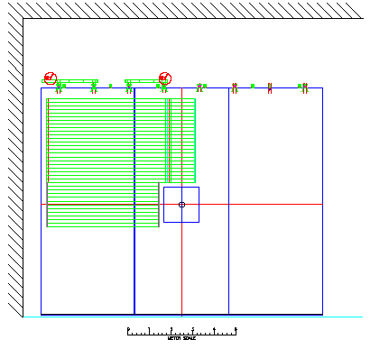
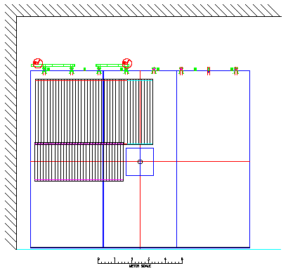
The first point is to consider that the Muon Identifier is naturally divided into 4 overlapping quadrants. Figure 1 shows the arrangement of the horizontal (or y measuring) tubes in what is called the A, B, and D panels of the Muon Identifier. Likewise, Figure 2 shows the arrangement of the vertical (or x measuring tubes) for the same panels. I will, for convenience call this Quadrant 1. Quadrant 2 would be the mirror image of Quadrant 1 through a vertical plane containing the beam. It would then consist of panels B, C, and E. Quadrant 3 is a mirror image of Quadrant 1 through a horizontal plane containing the beam. It consists of panels D, F, and G. Finally, Quadrant 4 then consists of panels E, G, and H. Therefore, Quadrant 1 overlaps Quadrant 2 through each using panel B, and it overlaps Quadrant 3 since they both use panel D. Furthermore, due to the way the quadrants overlap, one can consider each of the quadrants as independent trigger units.

Figure 1: The horizontal tubes, which measure y positions, for Muon Identifier panels A, B, and D are shown. These tubes would be used in finding the Quadrant 1, y projection muon candidates.

Figure 1: The vertical tubes, which measure x positions, for Muon Identifier panels A, B, and D are shown. These tubes would be used in finding the Quadrant 1, x projection muon candidates.
The first step in implementing the trigger would be to `OR' the horizontal tubes from panels A and B together to get a logical horizontal tube which runs the entire length from the left edge of the Muon Identifier to about 0.75 m to the right of the beam-line position. Similarly, the vertical tubes of panels A and D are `OR'ed together to get tubes which run the full height of the region.
Next, in order to understand what I show later, one defines the numbering of tubes within an quadrant. The vertical tubes of Quadrant 1 would be numbered from right to left beginning at the right-most tube of panel B right across the quadrant to the 96'th tube being the left-most tube of panel A. Similarly, for the horizontal tubes, start with the bottom of the panel D tubes and count upwards right across panel A ending with the horizontal tube top tube of panel A being tube 64. (This numbering scheme is not important except that it helps me get a little more specific in the next step. Also, I don't have my map with me while writing this so I don't remember the exact tube counts.)
The next step is to re-map that numbering into a scheme which is associated layer by layer with the trajectories of muons coming from the vertex. That means that if a straight line drawn from the vertex passes through tube 10 in layer 1, 12 in layer 2, 16 in layer 3, etc., all of those tubes would be said to be "behind" each other. I will then give them the same letter designation, say j. So a muon passing through all j-labeled tubes in every layer would point back to the vertex (and not have multiple-scattered).
The trigger must take into account the fact that the muons in passing through the Muon Identifier can multiple scatter. The exact amount of multiple scattering which can be expected from layer to layer can be calculated (or determined from Monte Carlo if one is lazy). Let's assume that that is about the width of one tube. (That's not far off, but it should be optimized.) Then we could expect that a real muon found in tube `j' could be expected to be in j ±1 or in tubes `i', `j', or `k'.
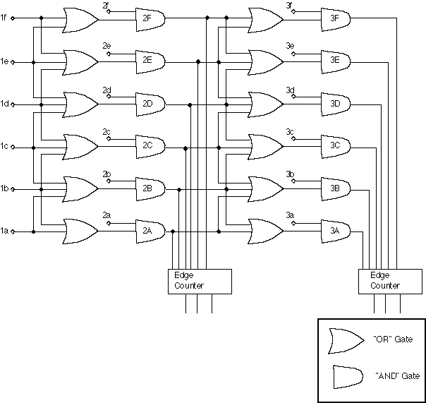
Once the above mapping has been done and the optimized width is determined for multiple scattering from one plane to the next, the conceptual implementation of the trigger is straightforward. Figure 3 shows how such a dynamic tracking trigger could be implemented for a three plane deep and 6 tube wide Muon Identifier.

Figure 3: A possible way to implement a three plane deep, 6 tube wide Muon Identifier. The input from the first tube in the first plane is labeled 1a, the tube immediately "behind" it (after re-mapping to account for tracks coming from the vertex) in the second layer is labeled 2a, etc. The "edge counters" which count how many muons went to a particular layer are described in the text.
Similar circuitry would be used for each projection in each of the four octants of the real Muon Identifier. The input signals from the from plane are numbered 1a through 1f in the example shown in the figure. The input signals from the next plane are numbered 2a through 2f and likewise for plane three. For PHENIX's Muon Identifier, it is rather obvious that it would be both wider and deeper.
The "Edge Counter" in Figure 3 provide a count of how many muon projection candidates penetrated to the indicated layer. They could work in the following manner:
Assume one has hits which provide outputs from the "AND" gates labeled "3B", "3C", and "3E". The "Edge Counter" would be presented with a 6-bit wide pattern which would be
011010
If this pattern (all outputs of the "AND" gates on a particular layer) is loaded into a "shift register" in paralled, then the pattern is clocked out of the shift register into an ordinary pulse counter, the transistions from strings of 1 to zeros will be counted. In this eample, it would count to "2". That would be the number of muon projection candidates in layer 3 of the Muon Identifier. Note that it intentionally allows for one muon to fire two or more adjacent tube, which they will. Of course, if two muons are within that range, only one would be counted. That is called "double-track resolution" and in our case it requires that two muons be separated by about 4 tubes to be counted as two with a high probability. The consequences of that would need to be Monte Carlo'ed, but it should not impact us much. Remember this is only one of the two projections.
Assume that one wants to allow for inefficiency in plane 2, tubes 2b, 2c, and 2d. One would "OR" together the outputs of the "AND" gates labeled 2B, 2C, and 2D, invert the output of that "OR" feed it along with the tube 1c signal into the "OR" gates in which feed into 3A and 3E. That allows for a miss in plane 2 to continue the track in a region ±2 tubes wide in plane 3, if and only if, there is not correct in hit in plane 2. It is straight forward to put that kind of logic into the entire system.
A second advantage is that one now has more flexibility in trigger definitions. What one does with the muon projection candidate counts is decoupled from the muon candidate search routines. One could have the actual implementation of the search routine in more sophisticated logic than hardwired "AND" and "OR" gates to allow for more or less stringent candidate searches and that would be decoupled from what one does with the projection candidate counts.