W. Wayne Kinnison, Walter Sondheim, Melynda Brooks, Joel M. Moss,
and P.M. McGaughey
Los Alamos National
Laboratory, Los Alamos, NM 87545
Table of Contents
- Abstract
- Physics Goals of the South Muon Arm of PHENIX
- The Conceptual Design
- Design Criteria
- The Conceptual Design
- The Magnet Performance
- Physics Performance of the South Muon Arm Magnet
- Summary and Conclusions
- APPENDIX A -- Drawings of Magnet
A conceptual design of the muon magnet for the South Muon Arm of PHENIX is
presented. An overview of the physics and mechanical constraints are described
as well as the results of magnetic and physics performance studies as compared
to the North Muon Arm magnet.
A second end-cap for the detection of dimuons in PHENIX, known as the South
Muon Arm, was proposed as part of the PHENIX/Spin proposal. More details about
the physics goals of PHENIX[1]
and PHENIX/Spin[2] can be
found elsewhere. For review purposes only, the major physics goals which
utilize the detection of muons in the end-caps will be presented here with the
emphasis being on how the physics goals drive the muon magnet designs.
The primary driver for the South Muon Arm of PHENIX is the enhancement of the
polarized collider experimental program. It significantly increases the dimuon
acceptance of the detector. The second end-cap not only essentially doubles the
acceptance of low-mass dimuon pairs where both muons go into the same end-cap,
but it also increases the mass range available for study and extends the
rapidity coverage for dimuons by allowing for one muon to go into each of the
end-caps.
A second goal of the South Muon Arm is to enhance the pA, pp, and
AA physics programs of PHENIX in non-polarized beam operations at RHIC.
Again, the advantages of the second muon arm are significantly enhanced dimuon
rates for the measurement of vector mesons, low- and high-mass (Drell-Yan)
dimuon pairs. The measurement of the possible suppression of some vector mesons
with respect to other nearby vector mesons places a design criteria on the
desired dimuon mass resolution obtained by the muon arms. To separate the
J/ resonance from the
  ' by
approximately 6
 a mass resolution at the J/
 of about 100 MeV/c2 is required. To separate the
  (1s) from the
  (2s+3s) by approximately
3
 , the mass resolution at the
  needs to be 190 MeV/c2. This document describes a design of the
South Muon Arm Magnet directed towards achieving these goals.
A conceptual design for the muon magnet for the South Muon Arm has been
generated. The design was based on the following criteria:
- The mass and momentum resolutions for muons in the South Muon Arm Magnet
should be at least as good as the same quantities as measured in the North Muon
Arm Magnet.
- The South Muon Arm should be as near to identical to the North Muon Arm
as is reasonably possible. That design goal helps to reduce EDIA of not only
the magnet but also various other detector sub-systems.
- The South Muon Arm magnet must be movable and it should be 30 inches
above the floor in order for it to use the same style of rail system as is used
by the central magnet and the central arm carriages.
- The South Muon Arm magnet must be approximately 1.5 meters shorter than
the North Muon Arm magnet. This is an integration issue. The South Muon Arm
Magnet must be movable and allow for the Central Arm Magnet to be rolled 1.5
meters south of its nominal operating position in order to provide service
access on the North Arm and to allow for clearance to roll both magnets out of
the detector hall.
- No individual piece of the South Arm Muon Magnet should exceed the
40-ton lifting capability of the existing overhead crane in the PHENIX detector
hall. This ensures that the South Arm Muon Magnet can be assembled in the
detector hall after the other major rigging operations have been completed and
possibly after the larger lifting capability is no longer readily
available.
With the above criteria in mind, a conceptual design was carried out. Appendix
A provides engineering drawings of that design. The design presented here has
two coils mounted to the piston. The conceptual design of those two coils is
based upon the requirements of the physics program. In designing the coils and
the piston, models were produced which kept as much steel as possible under the
coils to reduce the saturation. That permits higher current densities (as
compared to the North Arm Muon Magnet) resulting in a higher magnetic field. In
order to reduce the saturation of the steel under the coils and thus get an
 which is nearly the same as for the North Muon
Magnet, the piston was designed to be at a 12deg. angle. (The North Muon Arm
Magnet has a 10deg. piston.) The design parameters for the two coils are as
follows:
 Rear Coil:     Current density: 6,428,570 A/m2
                Cross sectional area: 0.04998 m2
                Current: 321,300.0 A
                Cross-sectional dimension: 8.33 cm thick x
                60.0 cm-long

Front Coil:     Current density: 2,857,140 A/m2
                Cross sectional area: 0.023334 m2
                Current: 66,668.5 A
                Cross sectional dimension: 3.889 cm thick
                x 60.0 cm long
Several different shapes for the front of the piston were considered. The
drawings included in Appendix A show a piston with a 45-degree chamfer starting
at 30-cm in radius. Since, as will be shown below, that configuration presents
the "best" field shapes in the region of the nose of the piston, it is
considered the baseline design.
Figures 2.1, 2.2, and 2.3 show the results of simulating the magnet using the
Vector Fields Opera2d software for this "Chamfer-30" model. As stated above,
this model is drawn in Appendix A. Figure 2.1 shows the magnetic field strength
in the air of the magnetic volume, Figure 2.2 shows the saturation of the iron,
and Figure 2.3 shows the potential lines throughout the magnetic volume. The
normal component of the field along lines at 12.5deg. and 15deg. were also
calculated and are shown in Figure 2.4.
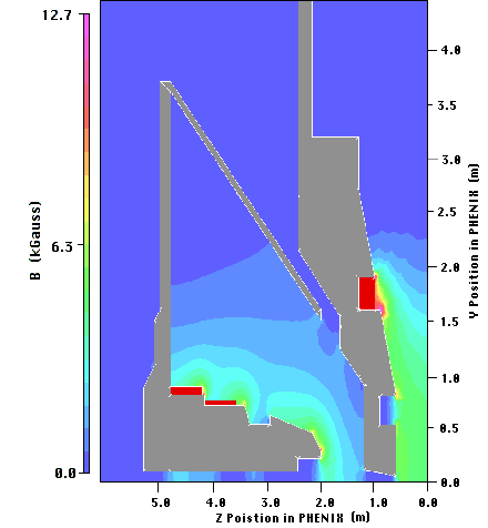
Figure 2.1: The magnetic field strength in the air region with the proposed
piston.
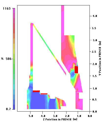
Figure 2.2: The saturation of the iron for the proposed piston model
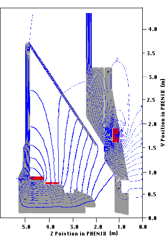
Figure 2.3: The potential lines through-out the magnetic volume for the
proposed piston model.
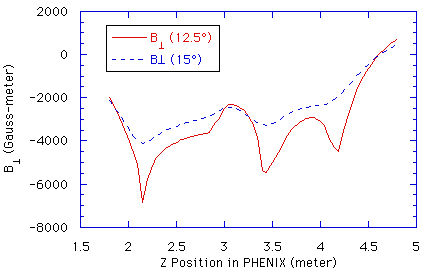
Figure 2.4: The value of the normal component of the magnetic field along a
line at 12.5deg. and a line at 15deg. in the magnet.
The reason for the chamfered nose on the piston tip is shown in Figure 2.5. The
figure shows the component of the magnetic field perpendicular to a line at
12.5deg. in the region of the piston tip for four possible configurations of
the end of the piston. The "30-chamfer" configuration has the end of the piston
chamfered with a 45deg. cut starting at a radius of 30 cm. In the "35-chamfer"
configuration, the chamfer starts at 35 cm. The "rounded" configuration has the
end of the piston completely rounded off, and the "snubbed" design has it no
chamfer at all. As the plot shows, the region of very high field is moved
farther from the Station #1 chamber location (from about 1.85 to about 1.95 m)
than the other configurations. The absolute size of the dip is also reduced.
Therefore, the "30-chamfer" configuration is the preferred design. Figures 2.6
and 2.7 show the magnetic field intensities in the region of the end of the
piston for the two extreme cases in order to demonstrate how the chamfer helps
to both smooth the field and pull the high-field region away from the chamber
location. The conclusion to be drawn is that the magnet should be designed in
such a way as to have sharp corners as far as possible from the active regions
of the Station #1 and Station #2 chambers.
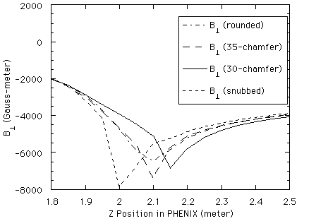
Figure 2.5: The component of the magnet field perpendicular to a line at
12.5deg. is shown for four possible configurations for the end of the piston as
described in the text.
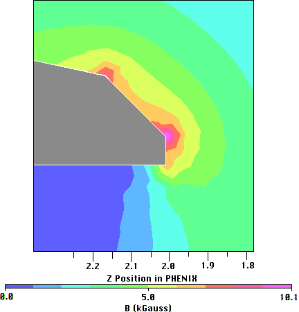
Figure 2.6: The magnetic field potential near the nose of the piston which has
been chamfered with a 45-degree cut at a radius of 30 cm (the "30-chamfer"
configuration).
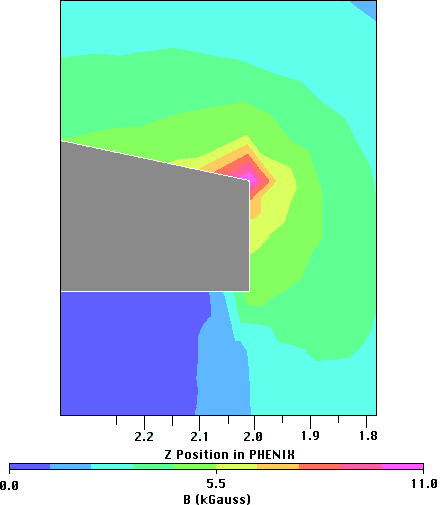
Figure 2.7: The magnetic field strength in the region of the piston tip which
has been snubbed off.
The line integral  has been calculated for this
design with all of the above models of the piston. Table 2.1 presents the
results of that part of the simulation. The overall performance of this magnet
is very similar to the North Muon Arm Magnet.
Table 2.1: The integral of the normal component of the
magnetic field along a line ( )from a
z-position of 1.8 meters, which is the approximate location of the
Station #1 chambers, to a z-position of 4.79 meters, which is the
approximate location of the Station #3 chambers. The integral is calculated for
the various piston models described in the text along five different lines. The
integral
  is also calculated. (The units are
kGauss-m and kGauss-m2).
   Angle  12.5deg. 15.0deg. 20.0deg. 25.0deg. 30deg.
                       "Snubbed" Model
   -10.002  -7.738    -4.937    -3.442    -2.549
   -29.578  -22.923   -14.048   -9.480    -6.821
                      "35-chamfer" Model
   -9.996  -7.695    -4.940    -3.449    -2.558
  -29.957  -22.843   -14.084   -9.503    -6.847
                      "30-chamfer" Model
   -9.889  -7.680    -4.938    -3.457    -2.564
  -30.371  -22.918   -14.108   -9.536    -6.871
A study was carried out to compare the physics performance of the proposed
design of the South Muon Arm Magnet in comparison to the North Muon Arm Magnet.
That work is reported in another PHENIX Technical Note and will only be
summarized here.[3] It should be
noted that in the study, the North Arm copper absorber was 28-cm thick and the
South Arm copper absorber was 12-cm thick. The final configuration of copper
absorbers is yet to be determined, but it is more likely to be symmetric. In
the study the chambers in the North Arm were located at z positions of
180, 348, and 600 cm from the nominal PHENIX interaction vertex. The South Arm
had chambers located at 180, 288, and 450 cm from the vertex.
Figure 3.1 shows a plot of the mass resolutions obtained at the  , J/
, J/ , and
, and  in both the
North Arm and the South Arm with 100-um chamber resolutions. As can be seen
from the figure, the South Arm performance in the regions of the
  and J/
 is at least as good as the North Arm.
The fact that the South Arm appears to be a little better than the North Arm is
due to the reduced copper absorber thickness. A study has shown that the
momentum resolution for the
  and the J/
 muons is the same in both arms. Consequently one can safely assume that if both
arms have the same thickness of material through which the muons pass, both
arms will give the same resolutions up to the J/
 .
.
On the other hand, the mass resolution in the region of the  is somewhat degraded and studies have indicated that it is
significant. In the North Arm the resolution of the
  is
220 MeV/c2 and in the South Arm it is 245 MeV/c2. The
difference is due to the fact that in the South Arm the momentum resolution in
the tracking region is a factor of 1.4 worse than in the North Arm.
Consequently, in the South Arm the mass resolution has a stronger dependence
upon the chamber resolution than is the case for the North Arm. That dependence
upon chamber resolution is shown in Figure 3.2. In order to try to overcome the
loss in mass resolution at the
  , the above mentioned
study looked at what could be achieved if the magnetic field in the South Arm
Magnet could be increased by 20%. In that case, the mass resolution in the
South Arm would then improve to 225 MeV/c2, which is almost
identical to the performance for the North Arm.
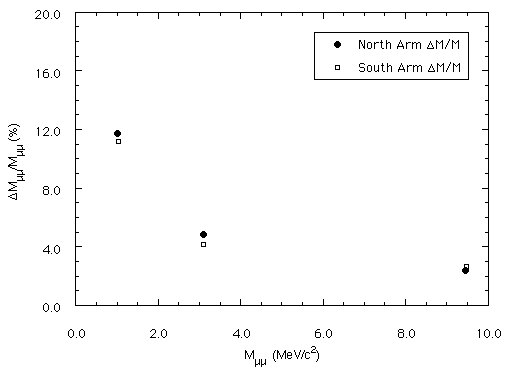
Figure 3.1: The mass resolution at the  , J/
, J/ , and
, and  from simulations in the two arms
with 100-um chamber resolution is shown.
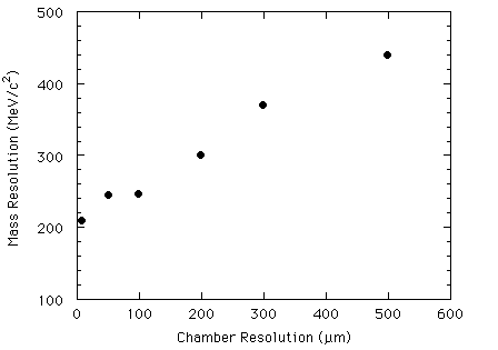
Figure 3.2: The invariant mass resolution of reconstructed muons from upsilons
in the South Muon Arm Magnet as a function of chamber resolution.
The conceptual design of the South Muon Arm Magnet which is presented here
would result in a magnet which would fulfill the design criteria and mechanical
constraints placed upon it and whose physics performance would be comparable to
the North Muon Arm. In order to accomplish that, however, the piston angle was
increased from 10 degrees to 12 degrees which will result in the South Muon Arm
having even less acceptance for  s than the North Arm. It
will, however, greatly increase the total acceptance for J/
 s, and
  s. It should be remembered in going
to the final design that any degradation in the performance of the magnet from
what is presented here will quickly degrade the spectrometer's momentum
resolution and thus the physics capabilities.
As pointed out above, in the final design care should be taken to consider
methods of avoiding sharp edges on the piston near the locations where the
Station #1 and Station #2 chambers will be mounted so that there will not be
large changes in the magnetic field in the chambers themselves. It is
suggested, also, that the final tip of the piston, which was studied here, be a
bolt-on piece. That will allow it to be manufactured separately from the rest
of the magnet and decouples the detailed design of the piston tip from the rest
of the magnet.
This Appendix contains a set of concept drawings of the South Muon Magnet which
has been used in the Magnet Performance and Physics Performance Studies
presented in this document. The drawings contained in this Appendix were
originally done by Walter Sondheim in collaboration with Orin Fackler, Bob
Yamamoto, and Joel Bowers. They are concept drawings only and should not be
used for construction.
This Appendix contains the followings drawings:
- Figure A-1: Full-cut assembly side view of the magnet
- Figure A-2: Head-on assembly view of the magnet
- Figure A-3: Detail of one of the two side pieces of the magnet rear plate
- Figure A-4: Detail of the center section of the magnet rear plate
- Figure A-5: Detail of the big donut of the magnet
- Figure A-6: Detail of a lampshade panel
- Figure A-7: Detail of the magnet piston. "30-chamfer" piston shown.
- Figure A-8: Detail of the small donut of the magnet
Mail the Author by clicking here
 resonance from the
  ' by
approximately 6
 a mass resolution at the J/
 of about 100 MeV/c2 is required. To separate the
  (1s) from the
  (2s+3s) by approximately
3
 , the mass resolution at the
  needs to be 190 MeV/c2. This document describes a design of the
South Muon Arm Magnet directed towards achieving these goals.
 which is nearly the same as for the North Muon
Magnet, the piston was designed to be at a 12deg. angle. (The North Muon Arm
Magnet has a 10deg. piston.) The design parameters for the two coils are as
follows:


 is also calculated. (The units are
kGauss-m and kGauss-m2).
 , J/
, J/
