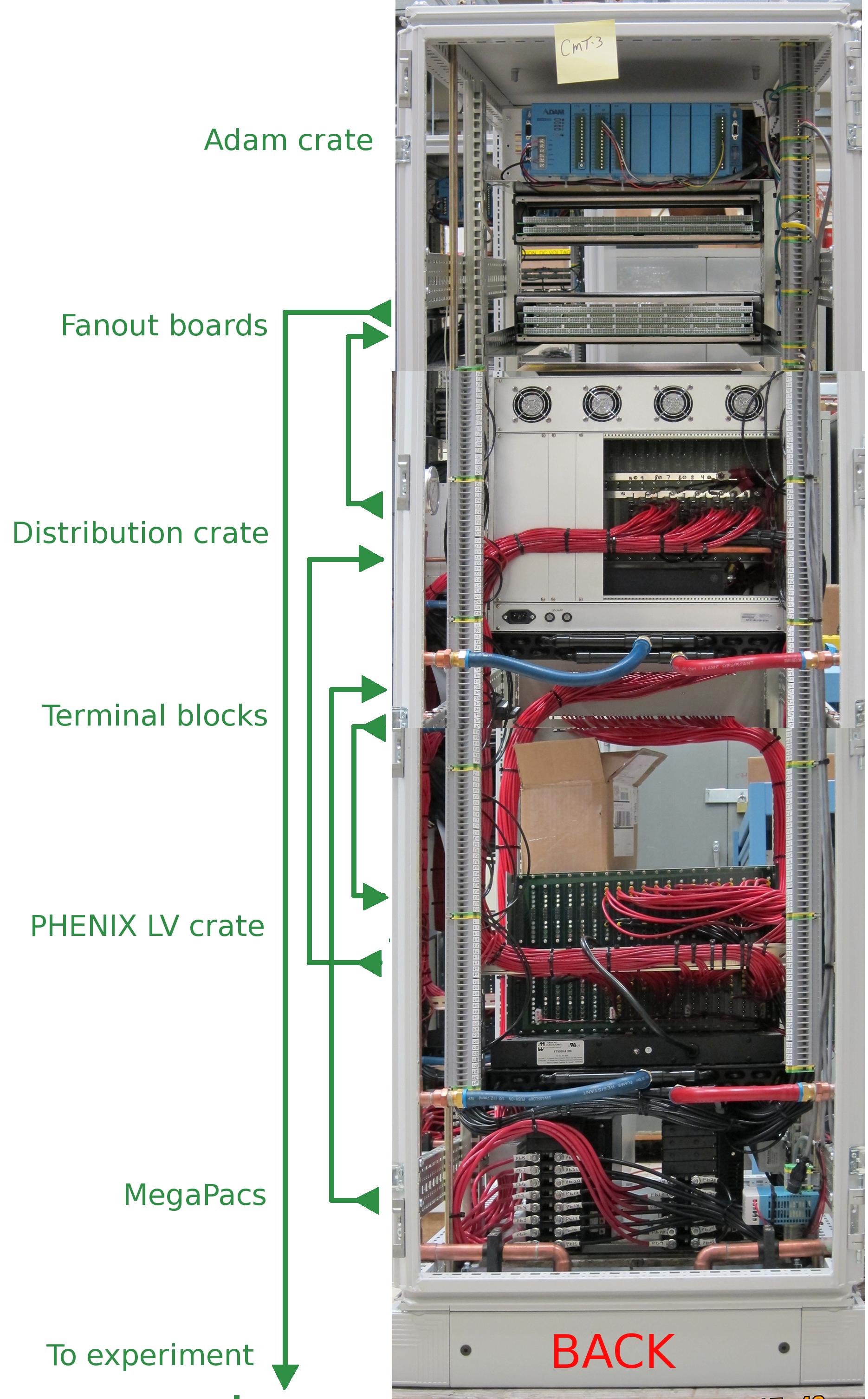
- the top crate is a standard Phenix LV supply crate,
- the next crate is a LV distribution crate,
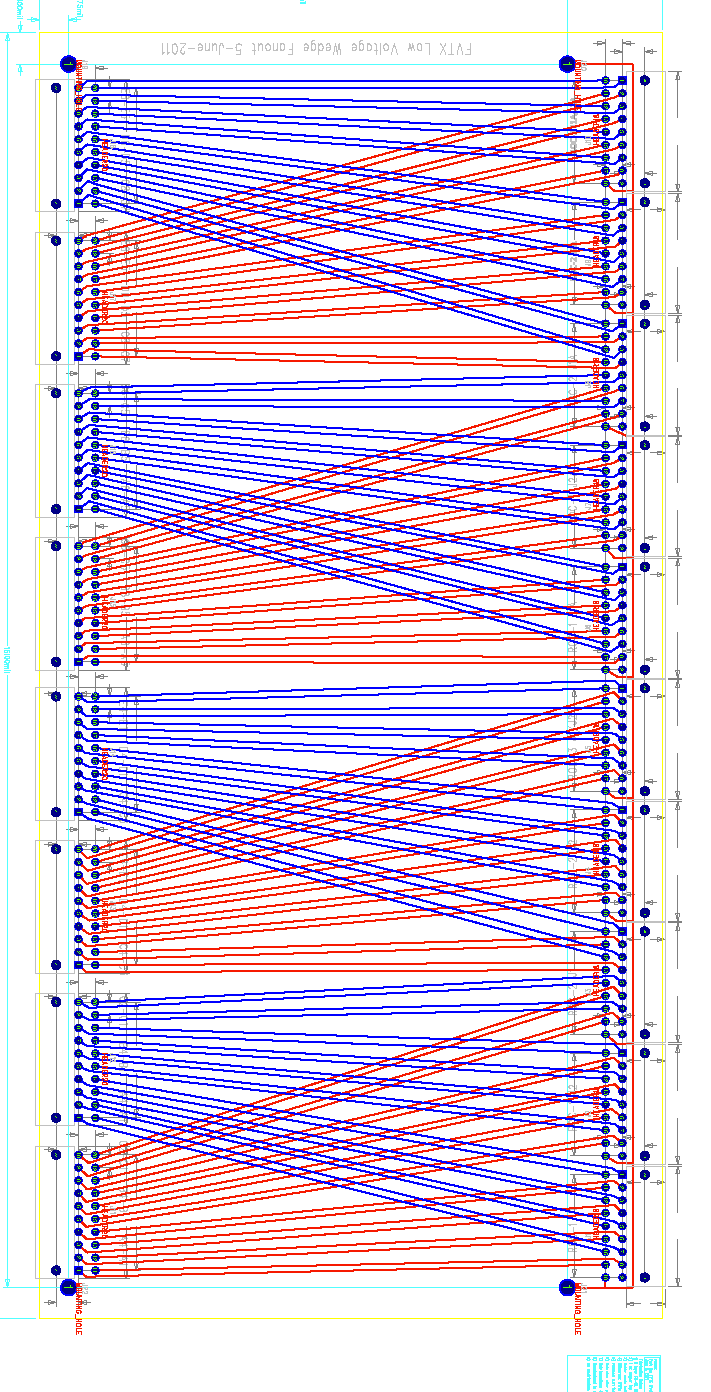
- below that are 5 fanout boards.
- on the bottom are Vicor Magapac supplies.
Vicor MegaPac supplies are located in the bottom of the rack. From there, power goes up to a row of terminal blocks, mounted on the front of the rack. From the terminal blocks, the power goes down to a standard PHENIX LV power supply crate.
One LV module is shown. LV power cables for both input and output are screwed in the back, no connectors.
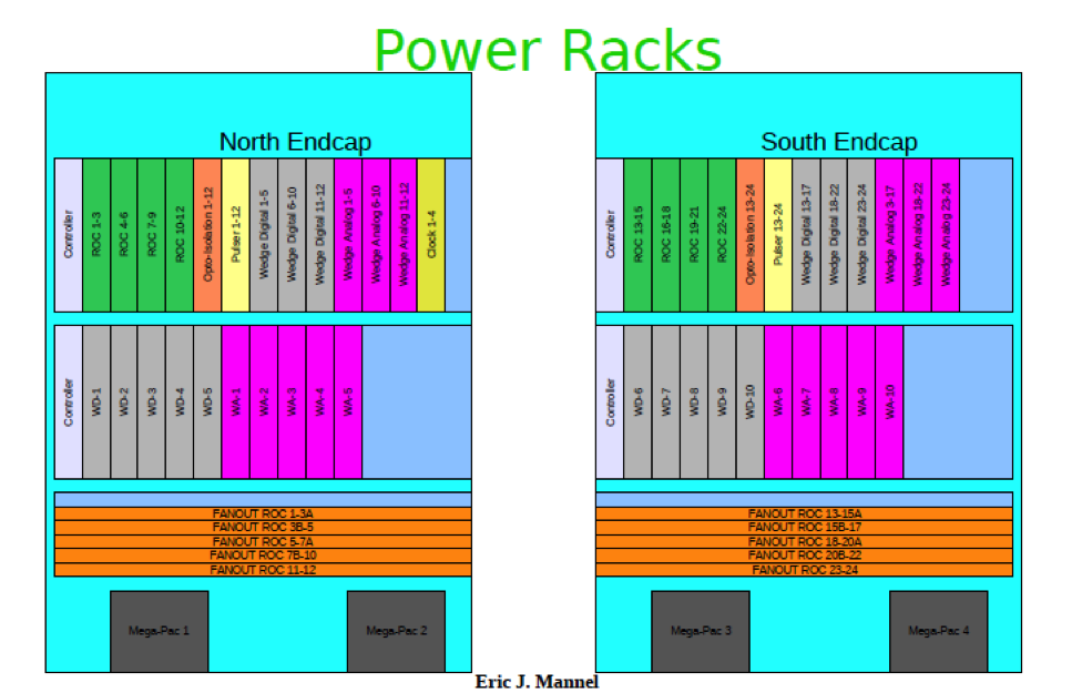
The assignments are as follows:
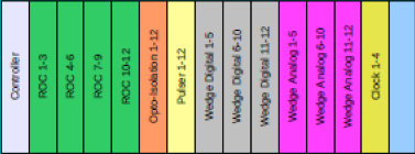
The last module, supplying power to the clock boards, is only needed once, and
is only present in the North rack.
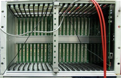
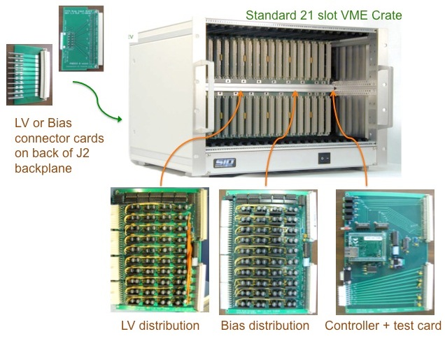
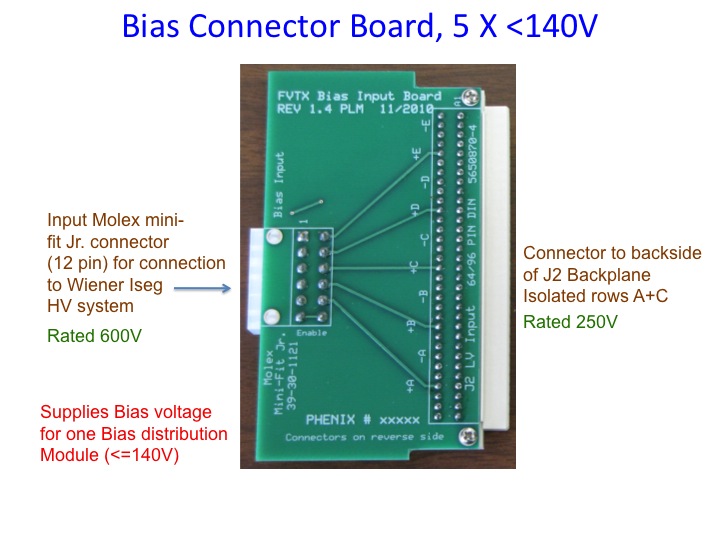
Power cables from the supply crate (above) are connected to the blades of the little connector cards that plug in the back of the J2 connector (of a standard VME crate) of the distribution crate.
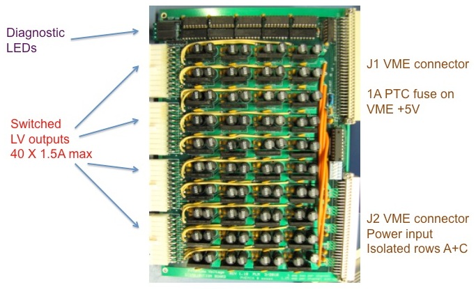
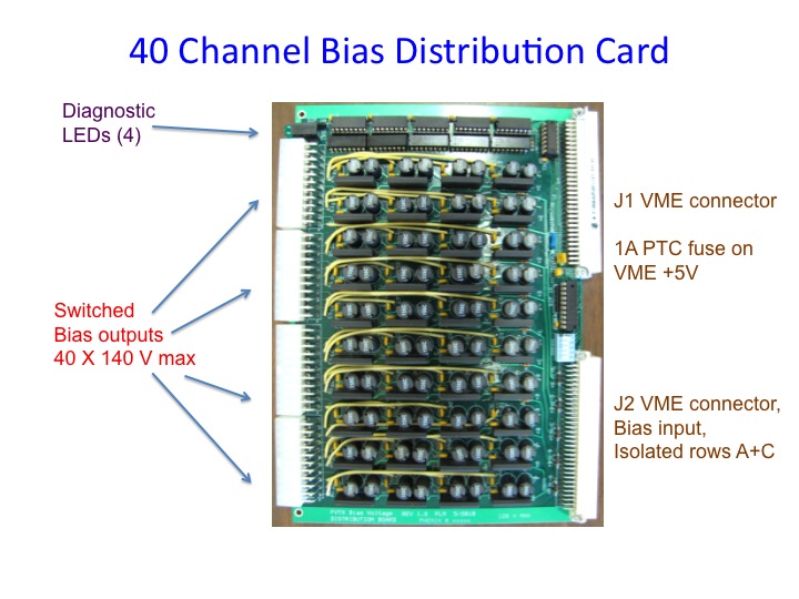
LV or Bias distribution cards take the power from the J2 connector, do some grouping and switching, and output power to connectors on the front. There are 10 cards per crate.
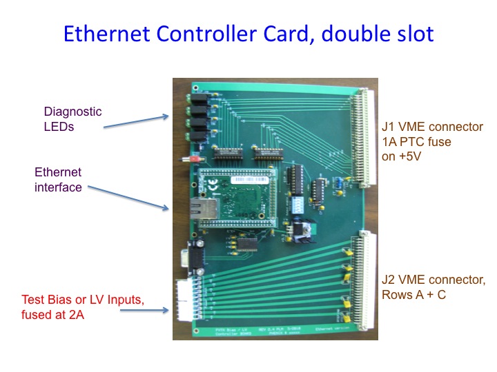
A controller card talks ethernet, and controls the relays on the ten cards.
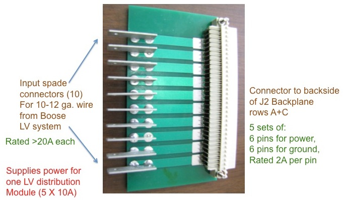
This is the little board that receives the power (5×10A) from the supply crate. It sits on J2 connector on the back of the VME backplane Note that the blades take considerable force to connect. So it is important to connect the supply cables to this board fitst, and then plug the board into the crate's backplane.
Output is on the front, with 4 20-pin connectors [LINK to connector specs]
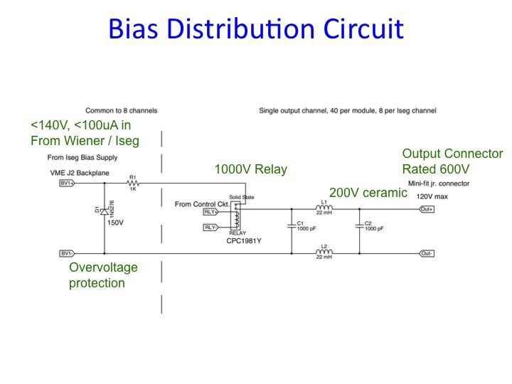
Here is the circuit diagram
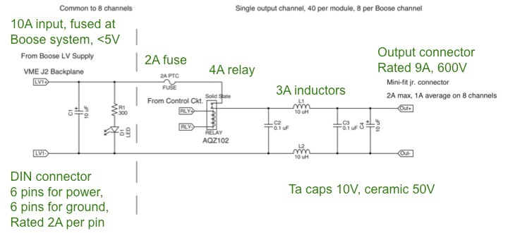
Output: mates to the VME J2 connector
Output on the front, 4 20-pin connectors [LINK to connector specs]
Here is the circuit diagam
Since they have 10 outputs, they service 2.5 ROCs each, so there are 10 of them.
These boards are 16.5×8" - very large. They are mounted below the distribution crate.