|
(1) Each disk has 3 holes in the perimeter, into which survey monuments are inserted after the disks are mounted in the cage. The suvey monuments protrude through lage holes in the cage to the outside, where they are visible. In this picture, I point out the holes corresponding to the disk that is mounted in it. Note there is no hole near the 6 o'clock position. The engineering drawings also do not show a hole there, see for example 111-PHX-02-3100 (RS, FVTX cage bonded assembly).pdf.
| 
|
|
The 3D model has 3 monuments per disk. In this drawing, only one is inserted
into the small disk. The monuments in th last disk (station 3) are
hidden by the big wheel cooling plate (lignt gray).
Plan 'A' for FVTX surveys is to leave 2 monuments per disk in place, and survey them after insertion of the FVTX into the VTX. The third ones, (middle ones in this picture) would be invisible at that point, and so holes in the shell were not even drilled. | 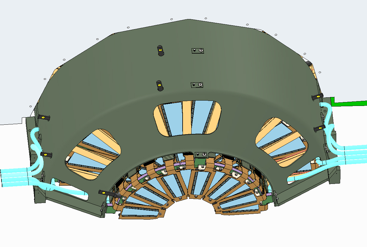
|
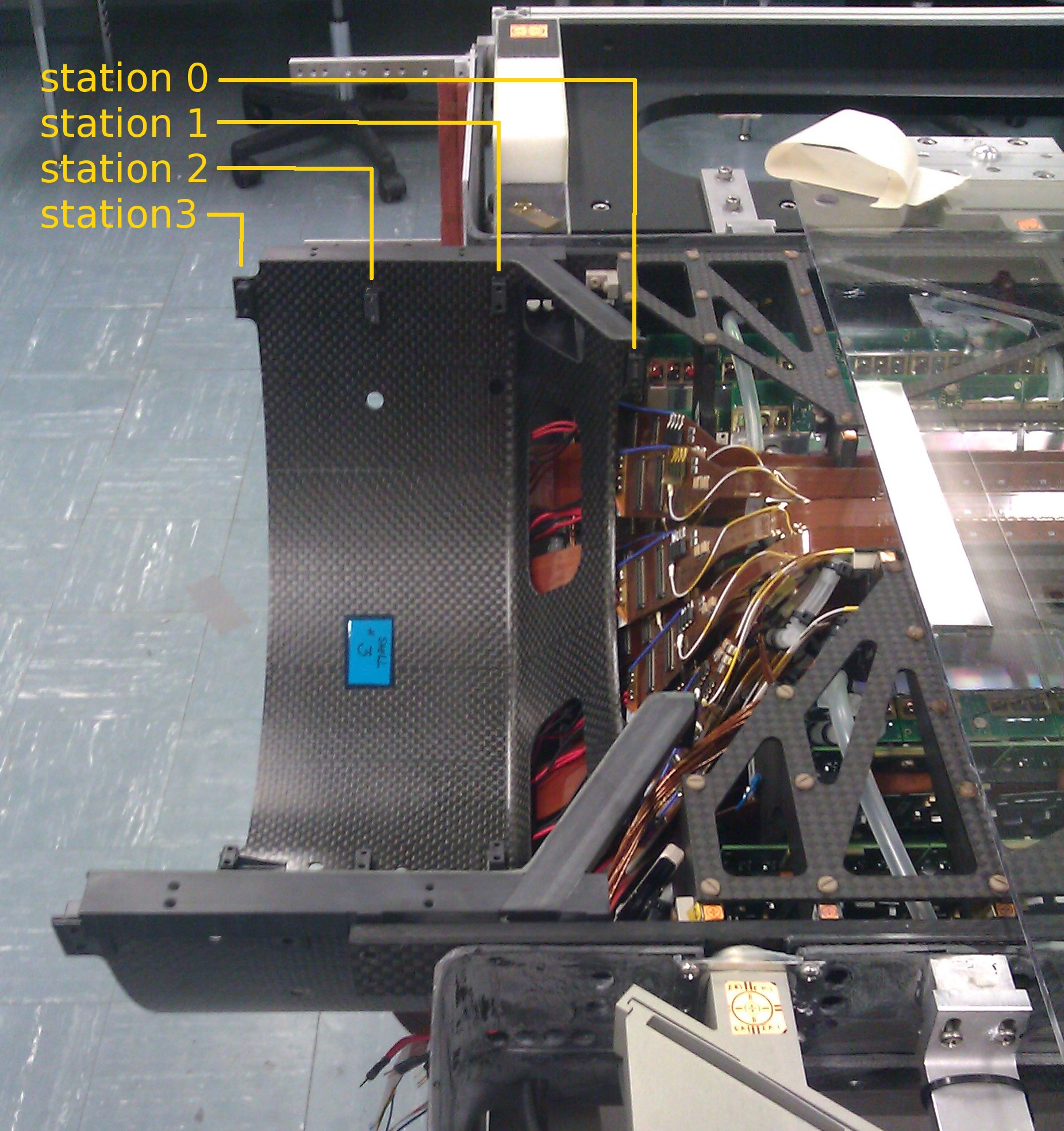
This picture was taken after the VTX was moved from 1008 to the lab.
Few if any of the FVTX monuments would be visible in this environment:
none for station 0,none for station 1, maybe 2 for station 3, and perhaps all 3 for station 3, which has other problems (see below).

| 
|
|
(2) Station 4: This disk is almost co-linear with the ROC. The holes where the survey pins go are in between the various cable bundles, and may look a lot more buried in real life. One additional problem here is that the cooling plate with the ROCs is not constrained at its inner radius, near the perimeter of the cage. The mount points of the cooling plate are near the outside radius. These plates also are not flat. In fact, the big wheel had to be pushed out of the way during the mounting of station 3 in order to to put the disk mounting screws in, and there was no space to insert the alignment pins. In the final assembly, even if we can get the survey monuments in, they will likely be pushed hard by the big wheel. | 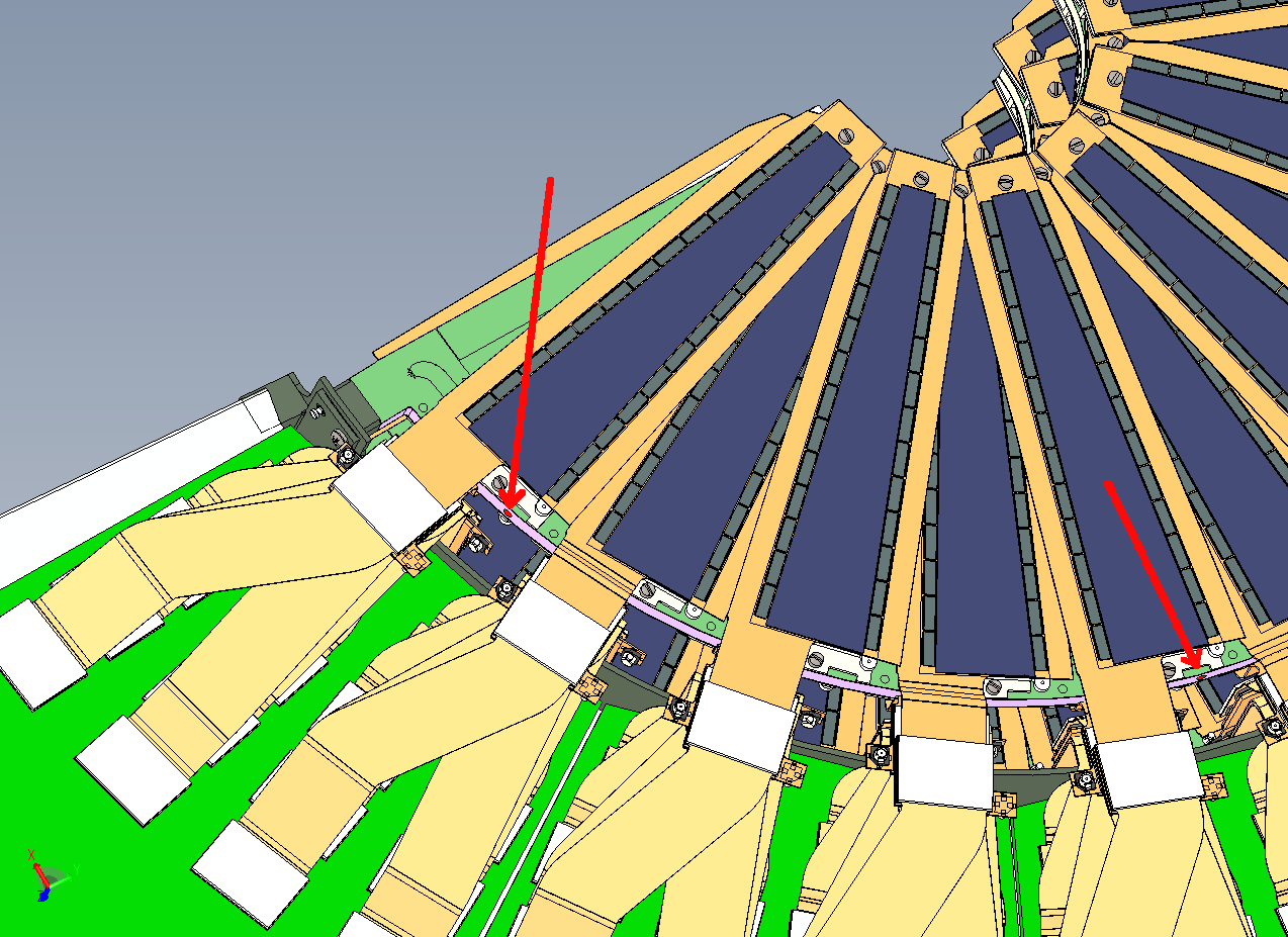
|
|
(3) Plan 'B' proposal for the surveys: Once we're integrated into the common VTX/FVTX frame, and later in 1008, a suvey will be done of each half of the VTX/FVTX. The only relevant FVTX thing visible is the flange of the cage. I propose to put marks as shown by the 4 yellow dots → Then we need to connect these targets to the number set we have from the metrology lab. This needs a survey in the lab. At what stage does this happen? I'm not sure the survey monuments can be mounted and seen when the finished cage is in the assembly frame. At this stage, we can use the assembly frame to clamp the cooling plate and free the station-4 monuments. Another option is to do this when the cage is lifted out of the assembly frame and is hanging from the transfer fixture, and before it is lowered into the VTX frame. This would need a temporary frame to rest the transfer fixture on while the suvey is being done. | 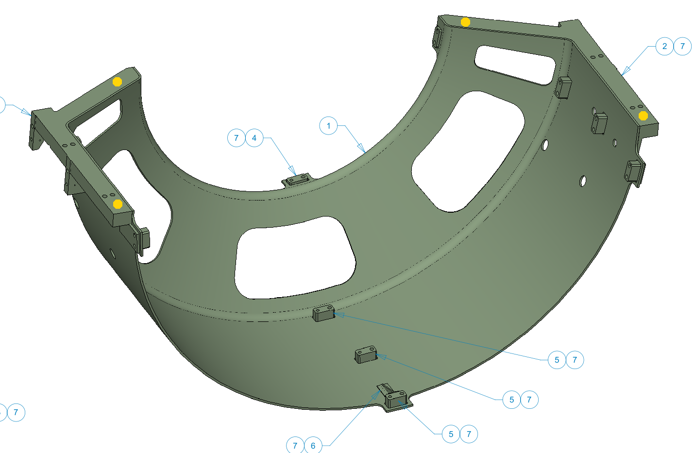
|
Hubert Van Hecke Last modified: Thu Sep 29 14:51:03 CDT 2011