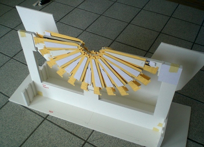
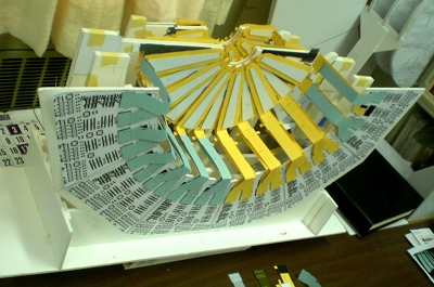
| Station 2. You can see the modules in 4 layers,
2 front and 2 back. The modules are detachable. The HDIs have
not yet been bent.
Click to enlarge→
|

|
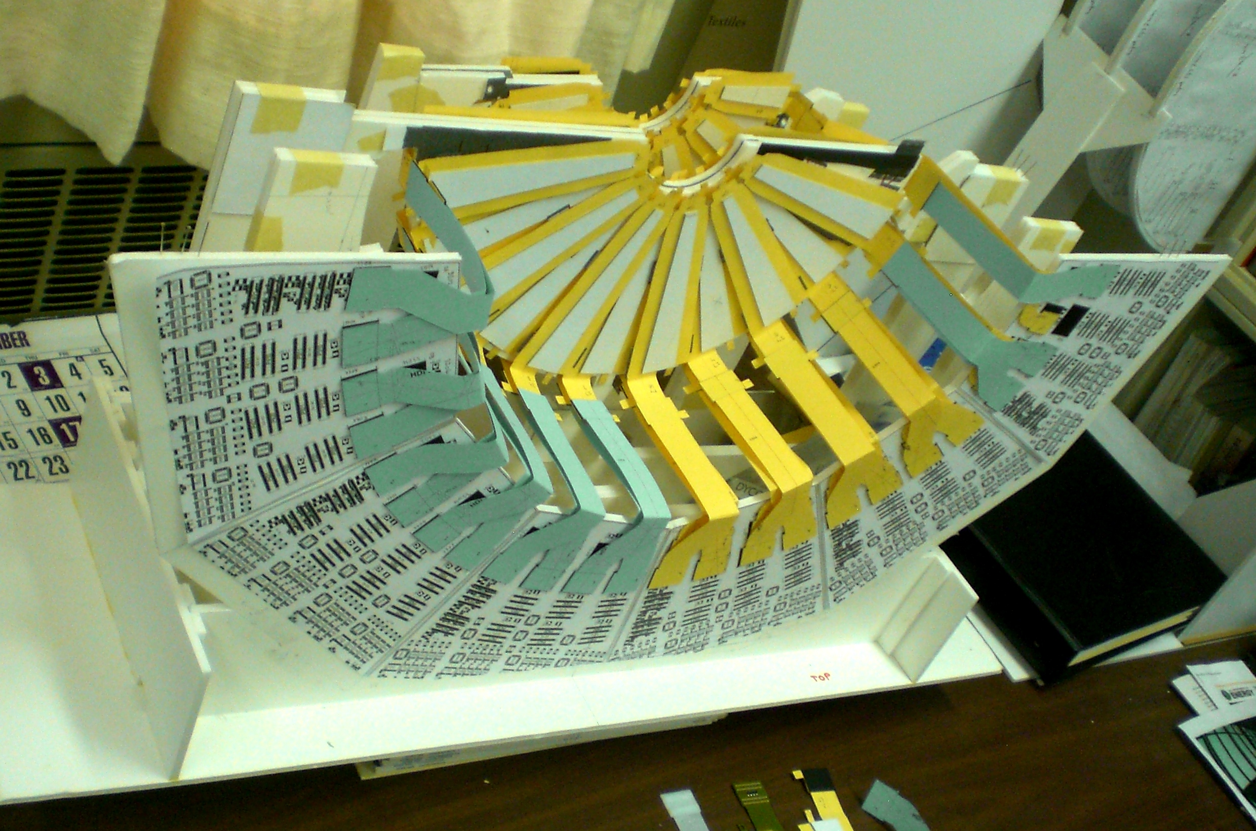
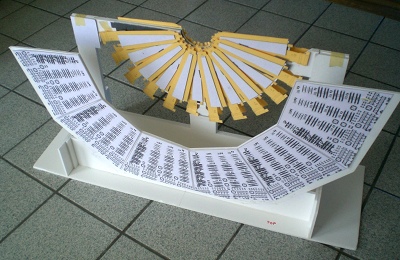
| Station 2 mounted in the stand. The back plane is the
central part of the big wheel.
Click to enlarge→
|
|
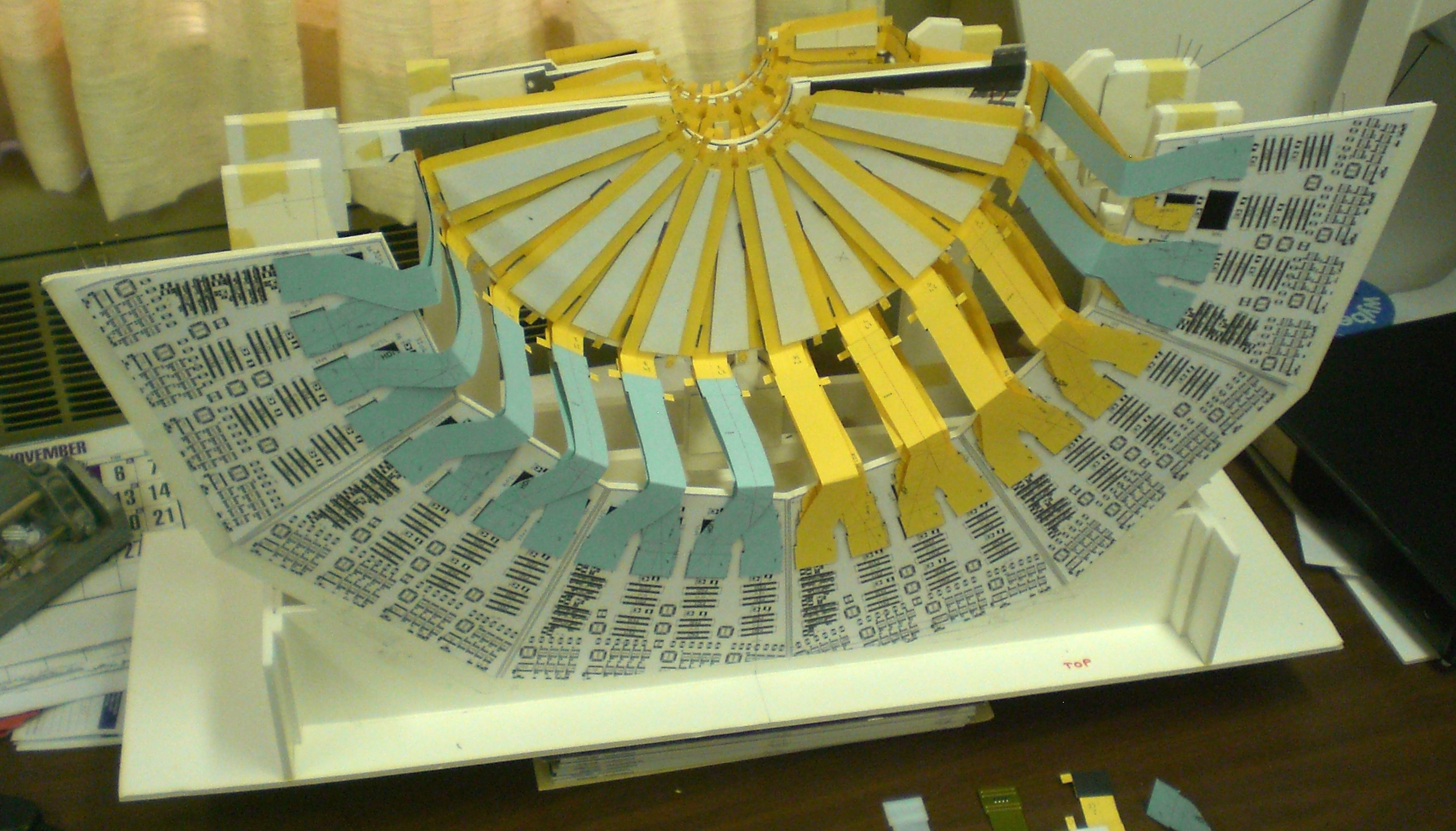
| View from the back, showing the ROCs.Only the inner
part of the boards, where the connectors are located, is represented.
Click to enlarge→
|
|
| This is the ROC board, with the station-1 cables attached, before
they are bent. On the top left, a station-2 connector pair is
modeled with refrigerator-magnet material.
Click to enlarge→
|
|
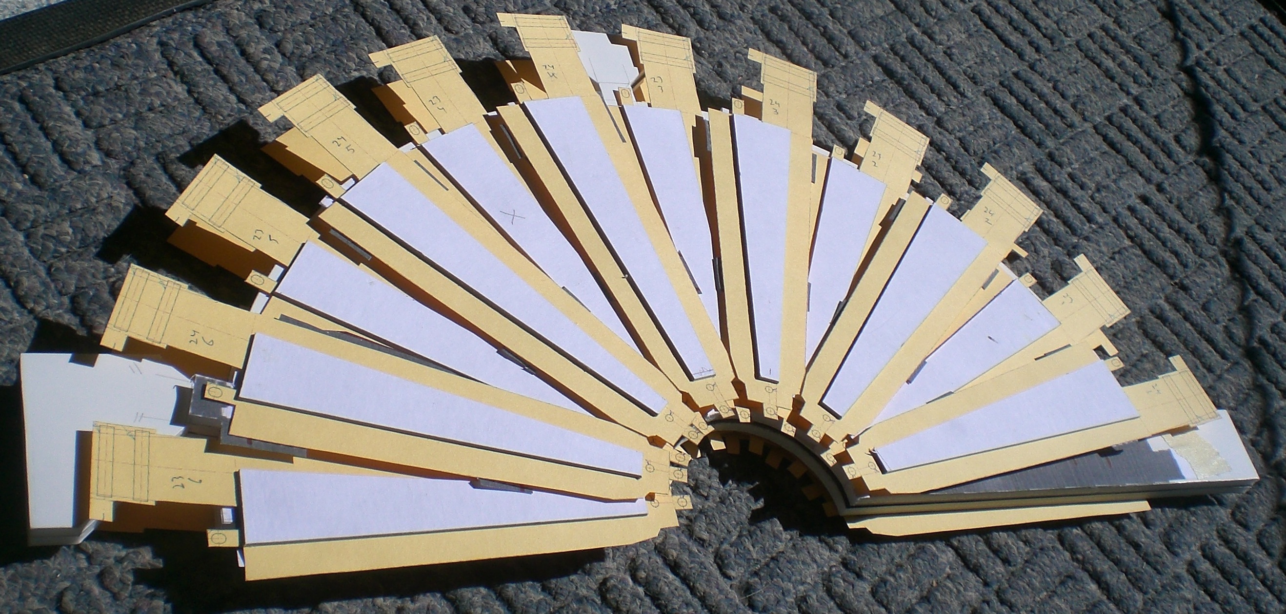
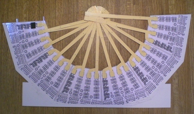
| This is the ROC board, with the station-2 cables attached, before
they are bent.
Click to enlarge→
|
|
| View of the corner of station 1, with bent cables attached.
Click to enlarge→
|
|
| Station 1, 2 and the ROC boards
Click to enlarge→
|

|
| Station 1, 2 and the ROC boards
Click to enlarge→
|
|
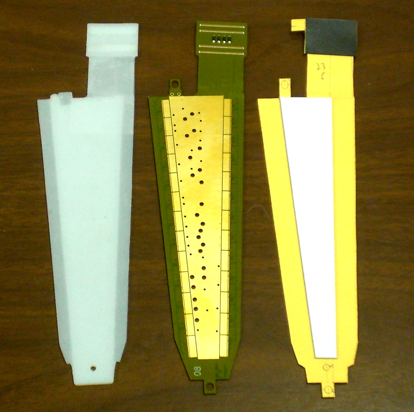
| One detector module, as a rapid-prototype, an HDI prototype
and a paper-and cardboard version.
Click to enlarge→
|
|
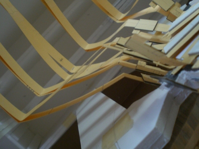
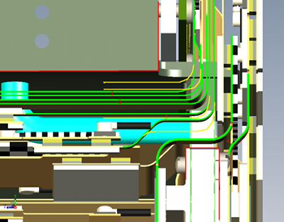
Of all assembly procedures, the bending of the HDIs and the
extension cables likely will have the largest errors/tolerances.
The cables are very stiff.
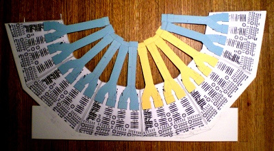
The most critical bends are in the extension cables (shown in green)
where they approach the
big wheel, and make a 90° turn from running in the z-direction to
going radially out to their connector attachments. Eight cables are nested as
they make this turn. In the current model, there is ~0.5 mm space between
adjacent cables. If the bend locations are off by more than this, it could
prevent a cable from reaching its connector.
The space available in this region is between the edge of the cage, and
the edge of the station-4 support board, both outlined in red. The radial
distance is about 16 mm. If we bend the cables in slightly different
locations (sketched in yellow), we can increase the inter-cable space
to 1-2 mm. To first order, the length of the cables remains the same.
Click to enlarge→
|
|