| (1) Barrel support structures (GFRP is G10) as they are currently in Pisa. The rings support the ends of the VTX ladders, and the blue posts tie them to the space frame. | 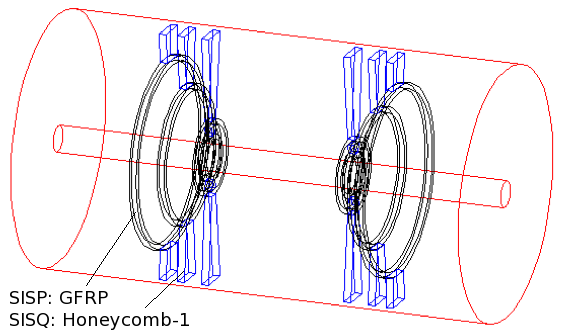
| ||||||
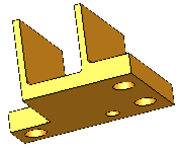
| (2) What is actually there? Looking at one of the mechanical drawings, the mounts have roughly the right shape, but need to be adjusted. In particular, the barrel 3 (red) and 4 (green) mounts are wider than in the model. Also, the barrel 1 and 2 ladders are mounted using the orange plastic blocks. Their mass is comparable to the carbon foam support (blue). ====> enlarge barrel 3,4 supports | 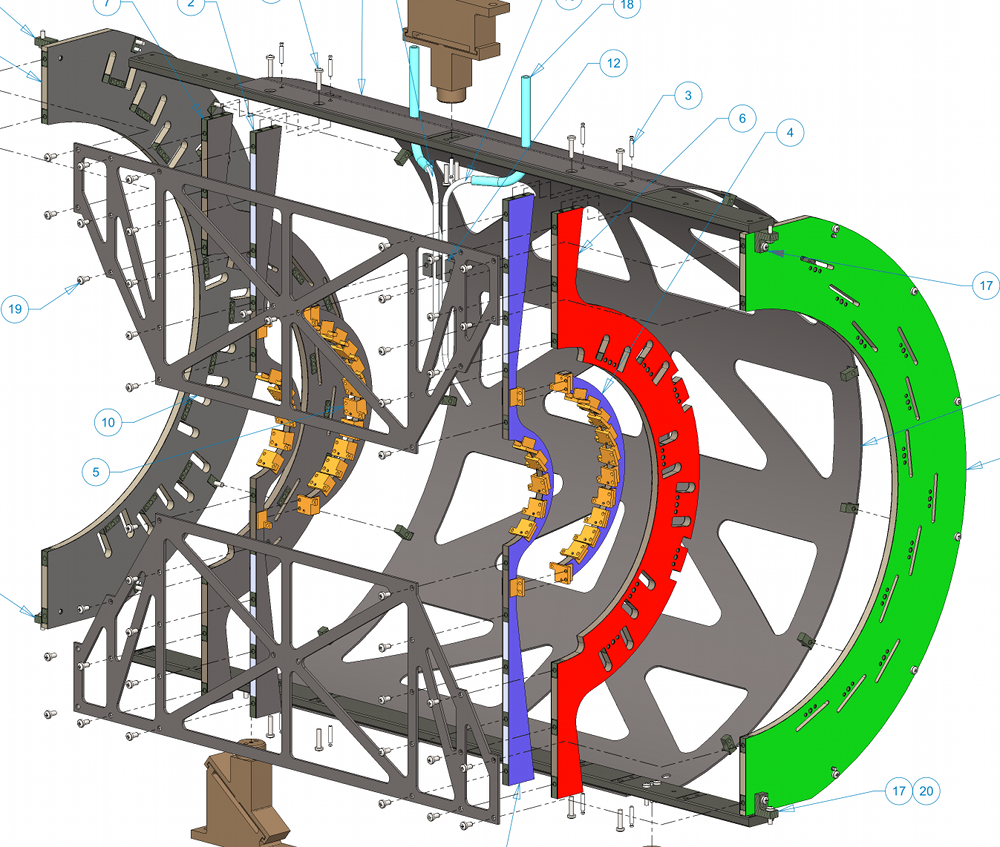
| ||||||
| (3) Done. Also note that in the original, the thickness of the support plates was incorrectly doubled. | 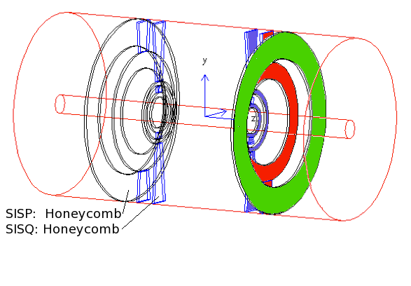
| ||||||
| (4) Cooling manifolds and feeder lines. The manifolds are modeled as hoops with 3.1×3.1 mm cross section. Since the density of Tygon is roughly the same as Freon, they were not modeled separately. Same for the nylon tees, elbows and hose barbs. This constututes 34g of stuff per side. From Mike Lenz, 12 Oct 2014: There are 92 tees and 116 elbows in the VTX cooling system. This alone weighs 29 g per side. | 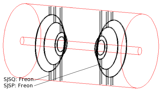
| ||||||
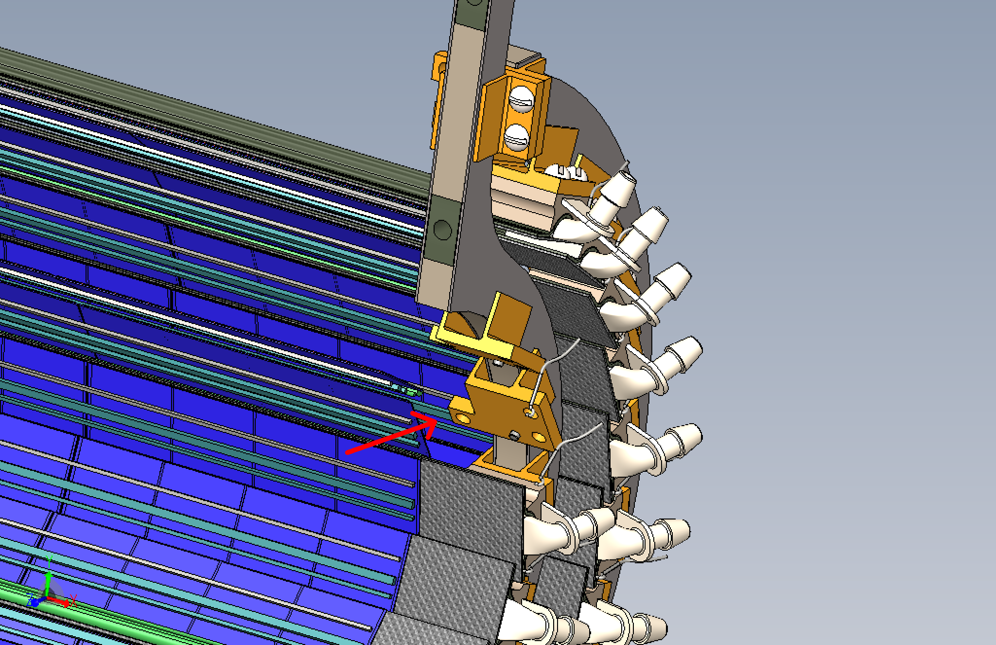
(5)
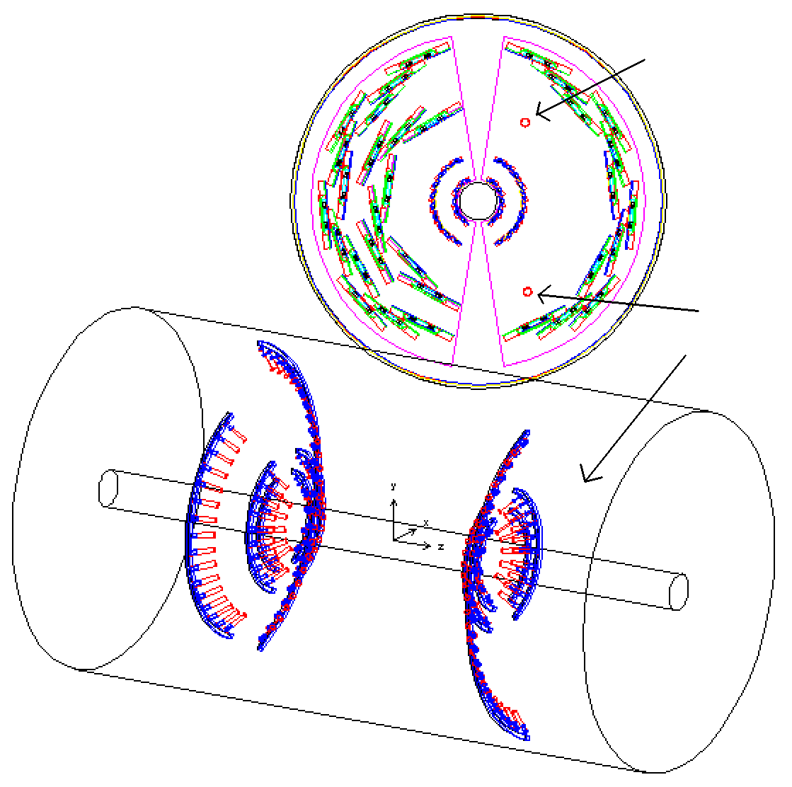
The circles in the previous section represent the arc of little tube sections (indicated by the yellow arrows) that make up the manifolds. Note the manifolds do not go a full 180° in reality. What is not represented are the short hoses that go from the ladders to this arc. These roughly triple the total amount of 'plastic' in cooling system. ====> Therefore, add this mass. | 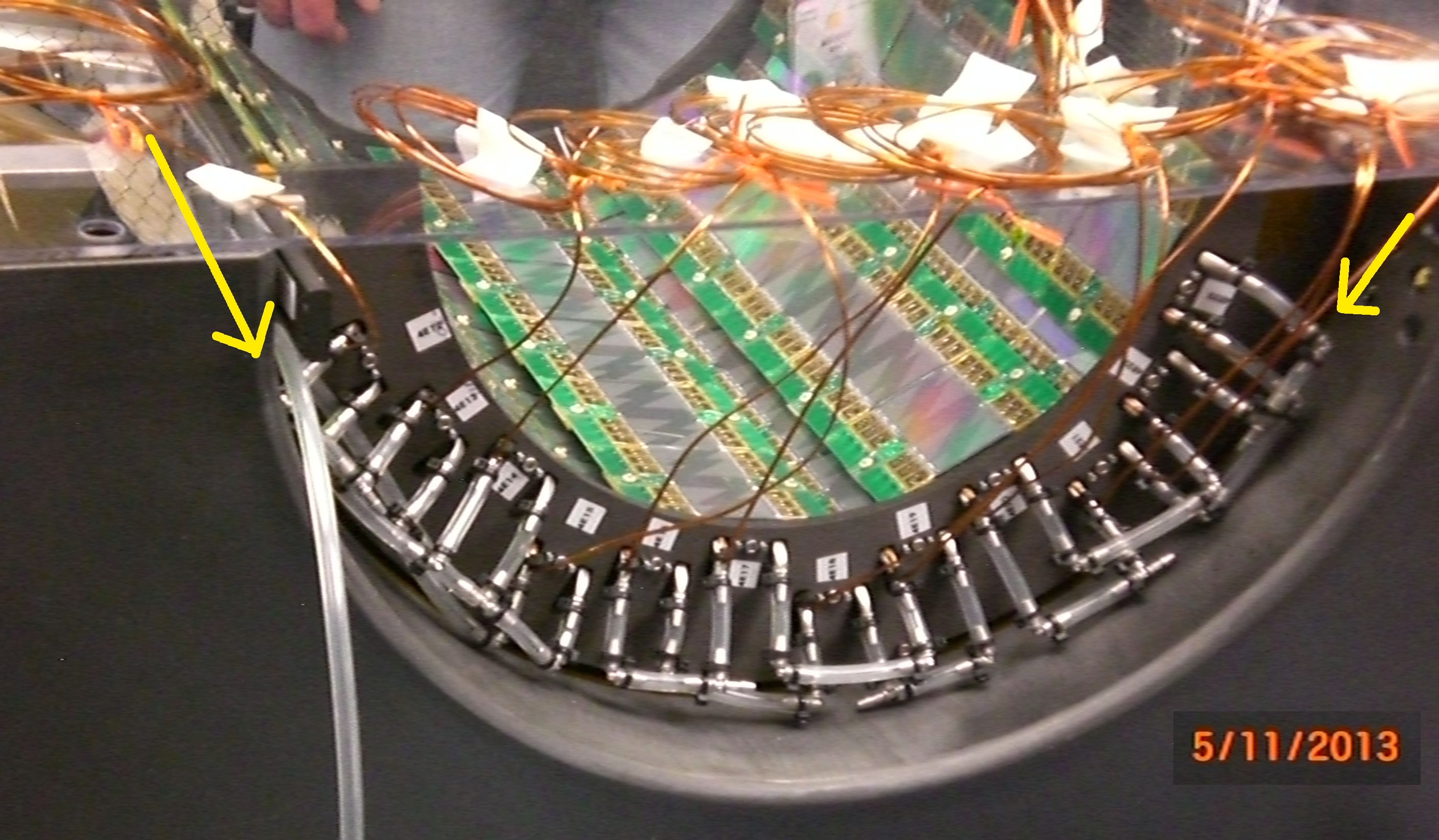
| ||||||
| (6) Adding the hose stubs. The number of stubs is not the same on each of the 4 half-barrel faces. From Mike Lenz, the number of hose stubs by face and barrel: face barrel-1 2 3 4 ------------------------- SW 5 10 0 24 SE 5 10 16 0 NW 5 10 16 0 NE 5 10 0 24 ------------------------- | 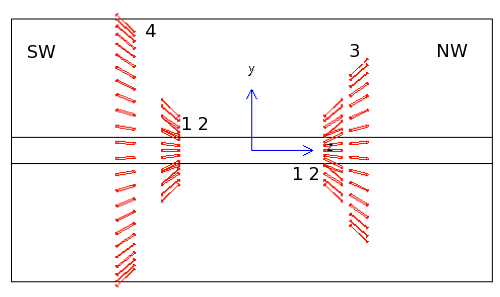
| ||||||
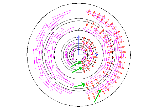
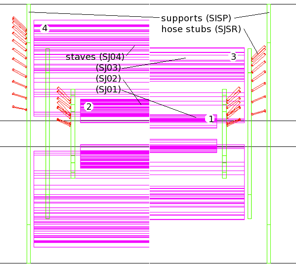
| (7) Place the stubs at the right radii, namely going out from each ladder. The magenta boxes are the ladder holder volumes. For Barrels 3 and 4, I place them at the middle ladders.
Top view (note only the West side stubs are shown):
| 
| ||||||
| (8) Modify the manifolds (black) so they attach to the ends of the stubs. Note that now they are also no longer North-South symmetic. | 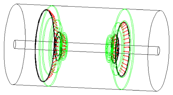
| ||||||
| (9) Finally, copy all this to the East half. Oops, cut the manifold hoops in half. | 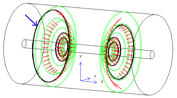
| ||||||
(10)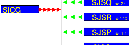 Check: there are 12 manifold arcs (SJSP), and 140 hose stubs(SJSR).
Other changes: the tubes are now 1/4" or equivalent, and the manifold arcs have been moved to resolve volume overlaps. | 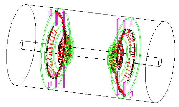
| ||||||
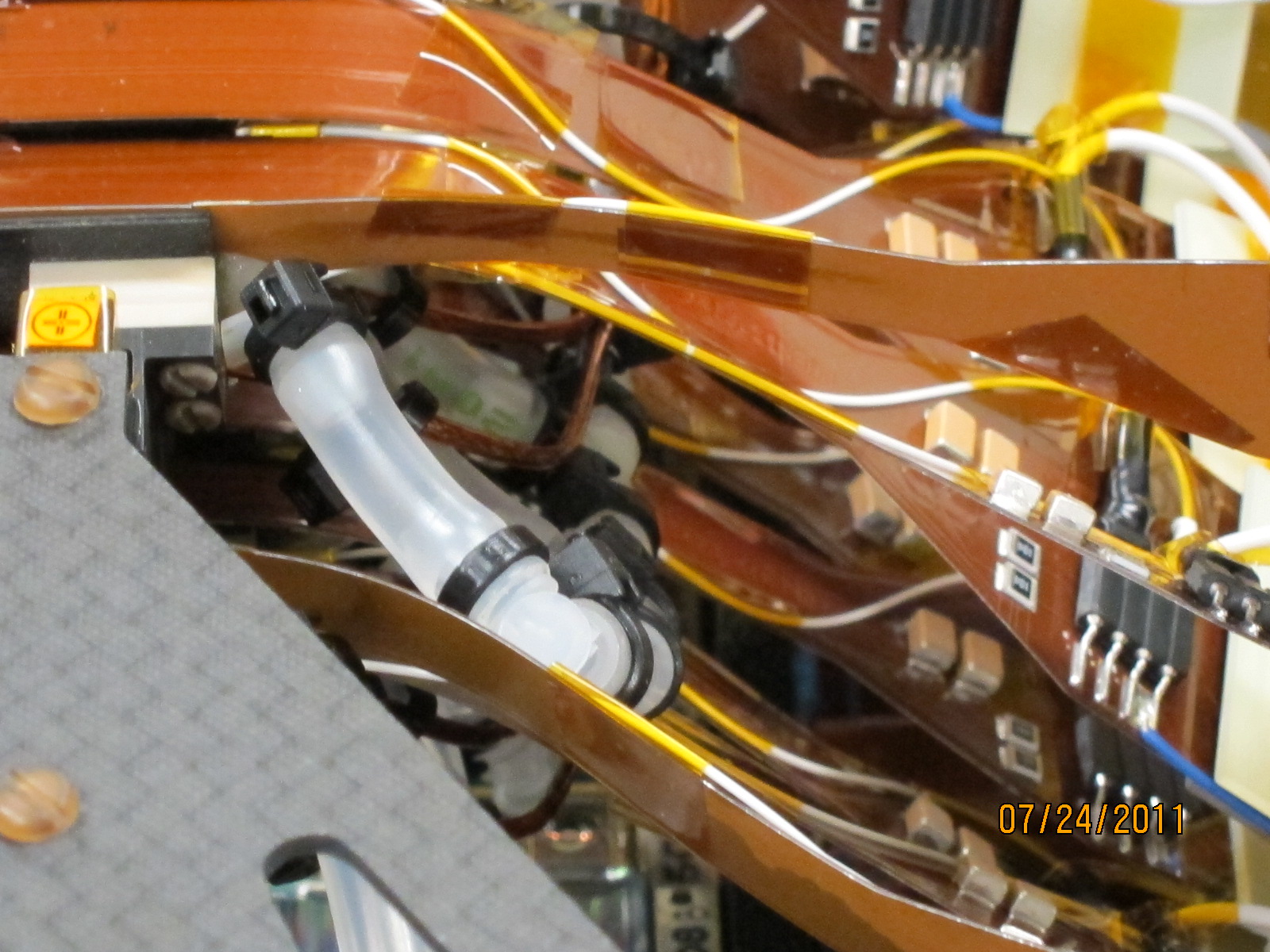
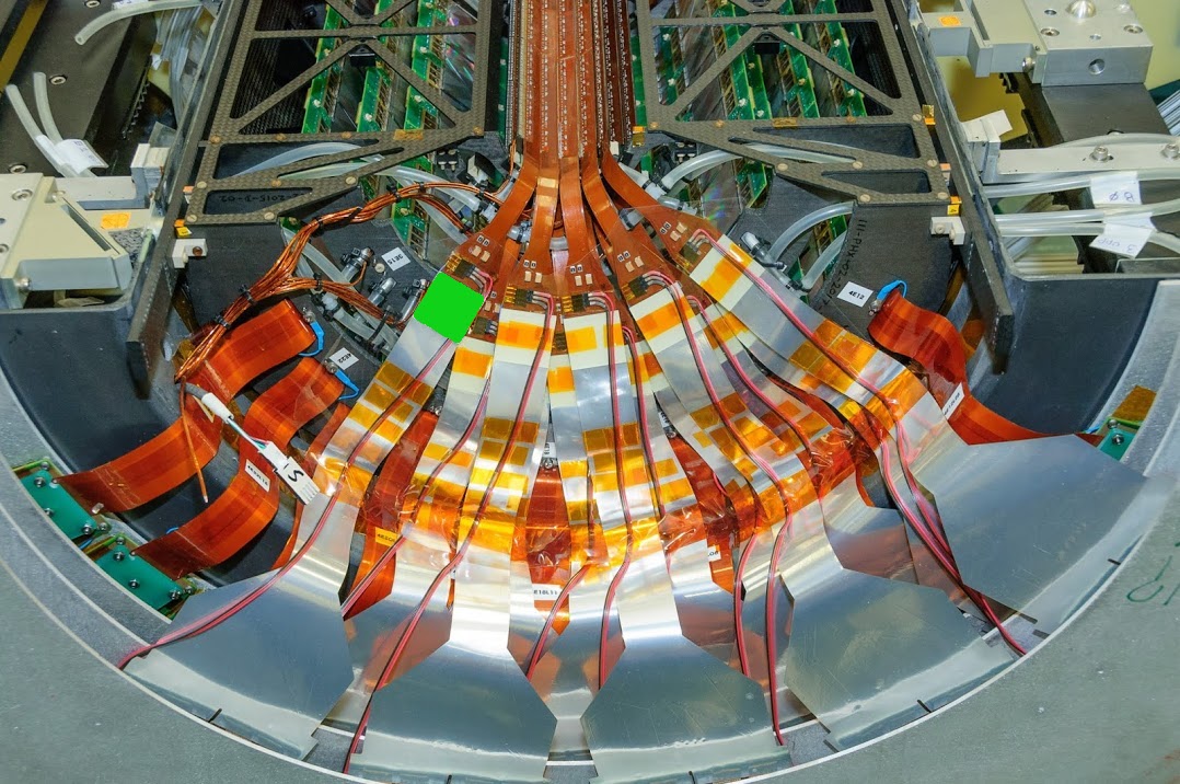
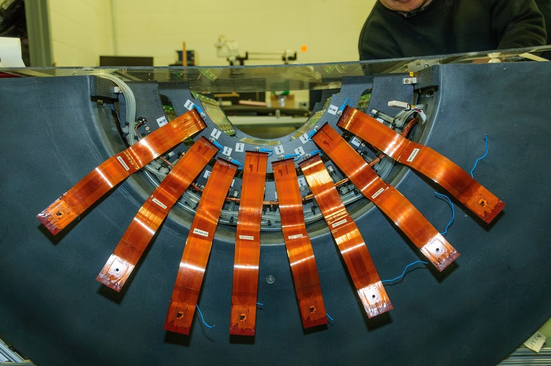
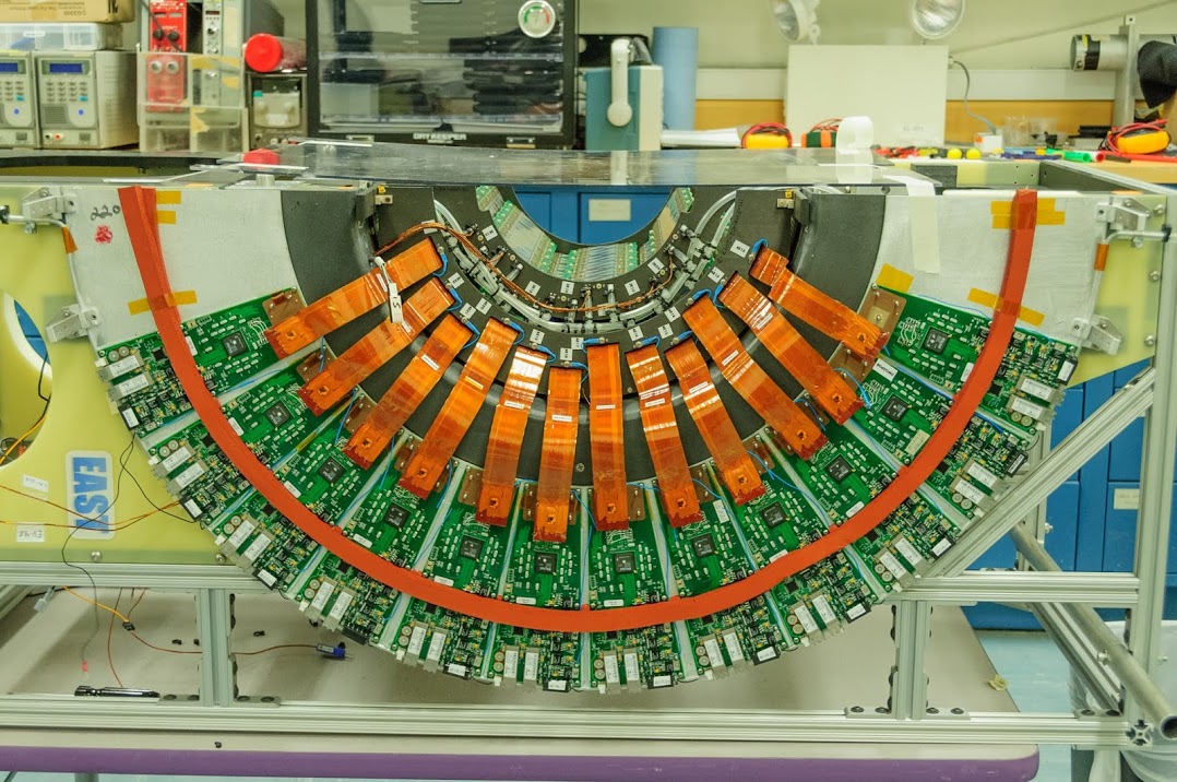
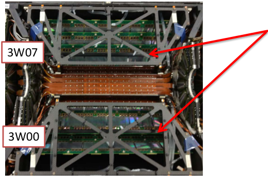
| (11) Next: cables and connectors: Currently, cables are modeled as disconnected material sheets, rather than individual items. SICC is a flat disk, SJCC a thin partial cone and SKCC a thin partial cylinder. Note these do not interfere with the new cooling manifolds.
The cables are thin, and the only thing that represents mass are the connector boards visible in the Barrel 1,2 photo, one of these is highlighted in green. This is a g10 board. | 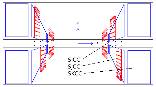
| ||||||
| (12) Join the cable sheets SICC, SJCC, SKCC into a single polycone (PCON), and move it so it does not bang into the FVTX cage. | 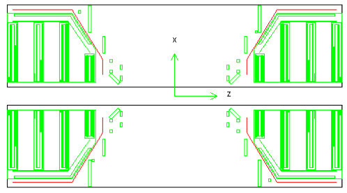
| ||||||
|
(13) Update April 2016 (Sanghoon and Hubert): the inner radius of the cable sheet was too small, so it was extended inward. Also, I measured the position of the little connectors on the ends of the barrel 1,2 HDI's. 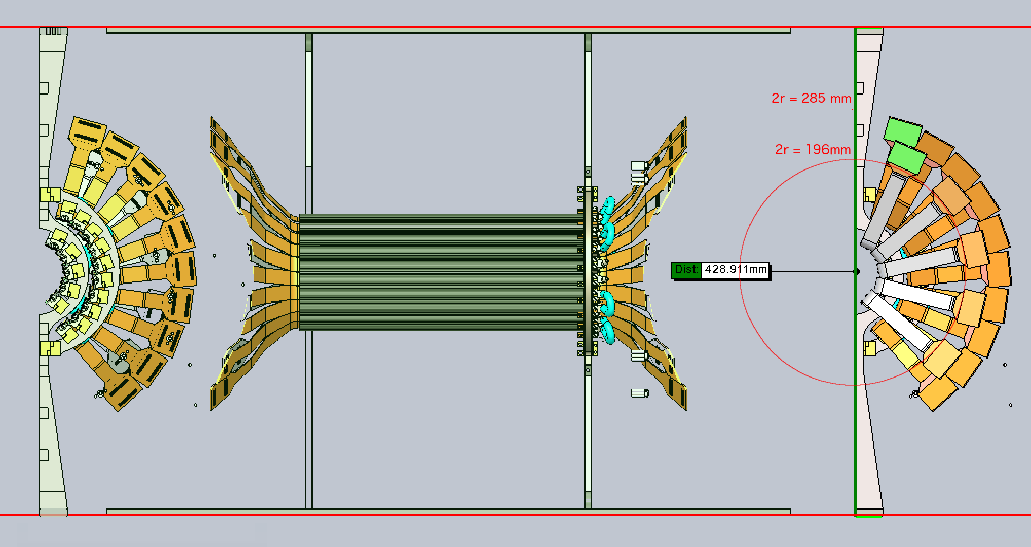
Side view of the VTX end, → | 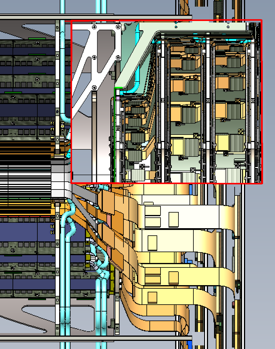
| ||||||
| (14) There are small plastic clips on the supporting arcs, and the ladders clip into these. Volume is 461 and 610 mm2, respectively. I'll use 'resin' for the material since is already was defined. 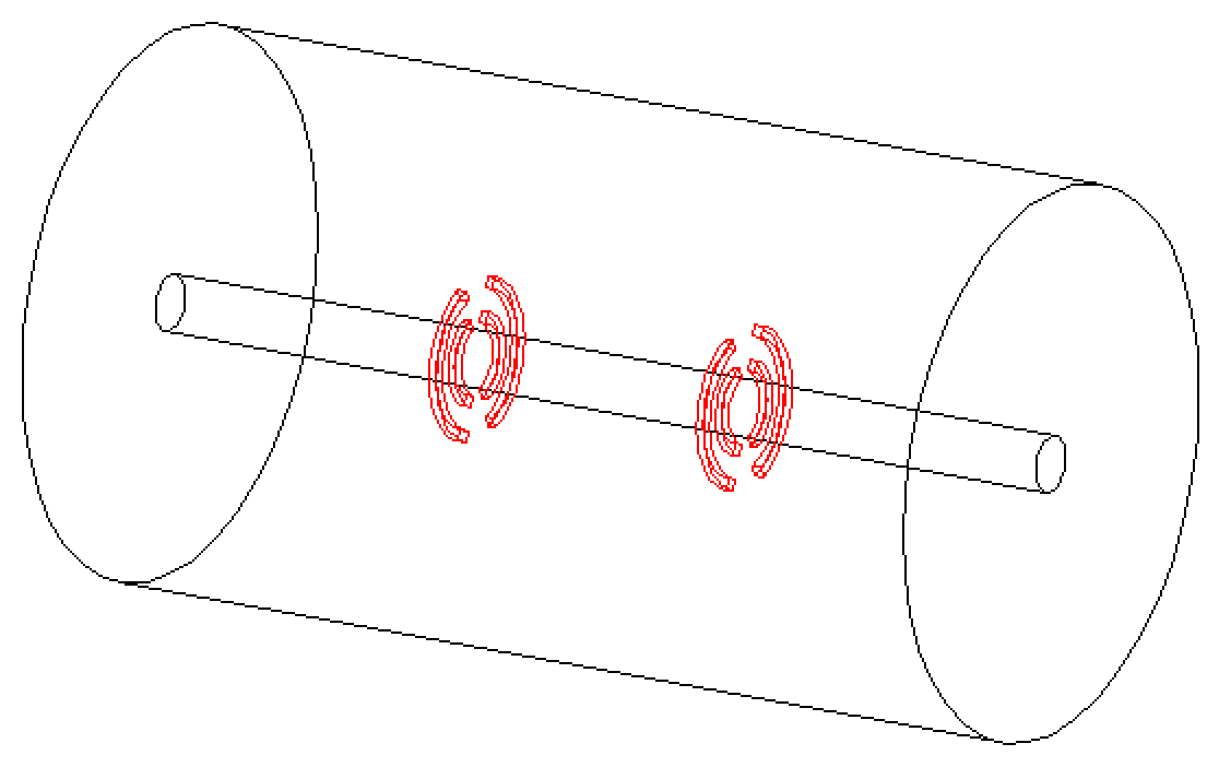
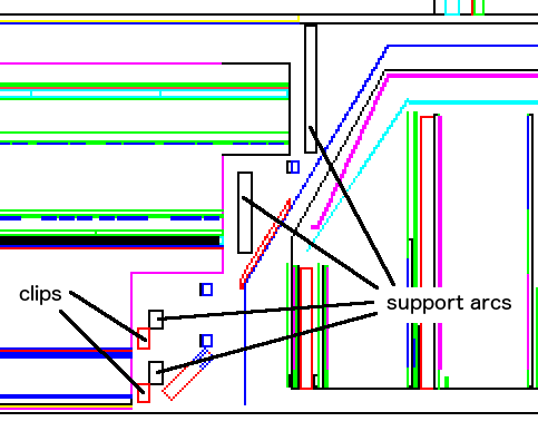
I represented the rows of clips by a smooth arc, having the same total density as the clips (volumes SISO). |

| ||||||
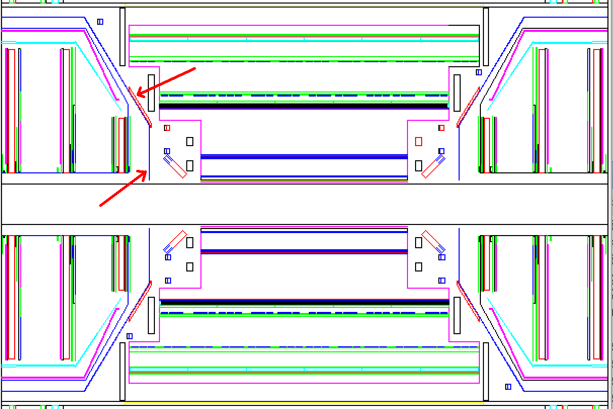
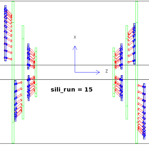
| (15) For run 14, the tees and elbows of the stripixel plumbing were replaced with stainless steel. This is modeled by inserting some stainless into the hose stubs and the manifold arcs. Before run 15, the pieces on the pixel barrels were also replaced with stainless. The picture is for run 14, and shows the hose stubs in red, with stainless bits in blue at the end where they connect to the manifolds. The manifolds consist of stainless arcs (blue) and freon arcs (red) side-by-side. For run 14, barrels 1 and 2 are still just plastic. The size of the stainless pieces is adjusted such that the total weight comes out to 233g in run 14, and 357g for run 15 and later.
How to switch this on/off: in pisa.kumac, set variable SETRHIC. If >=14,
you get the stainless on the stripixels, >=15 you get stainless couplings
on all 4 barrels. You can check this by running
mass6.kumac at the GEANT> prompt when you run pisa.
| 
| ||||||
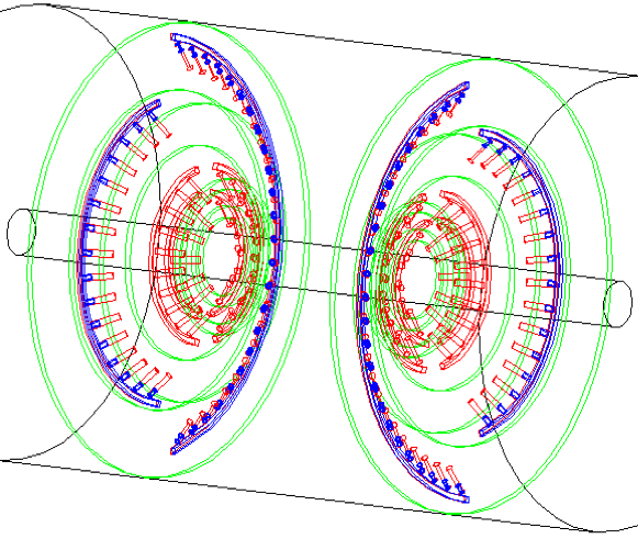
| (16) In 2013, the East half of the VTX was removed because of massive leaks. I added code that removes the new stuff if the year (set in PISA.kumac) is 2013. Left: before, right: after. Apr 2016 | 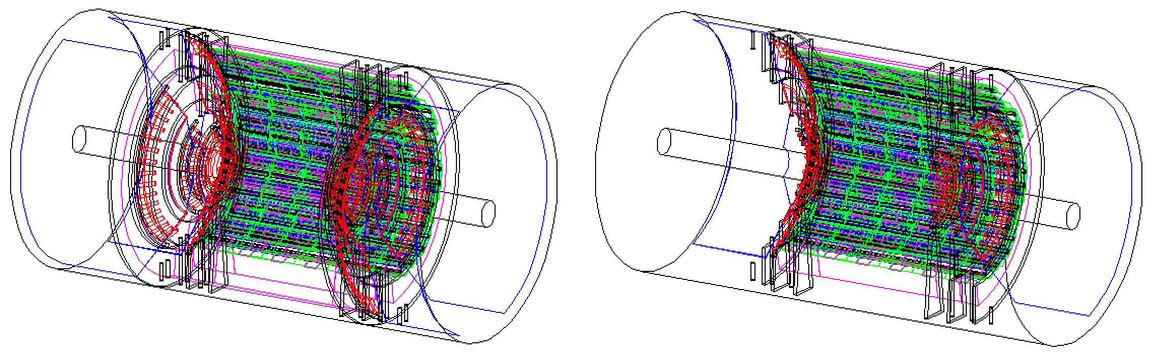
| ||||||
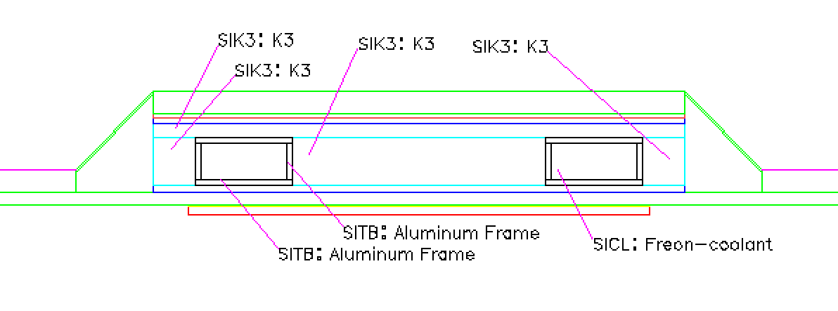
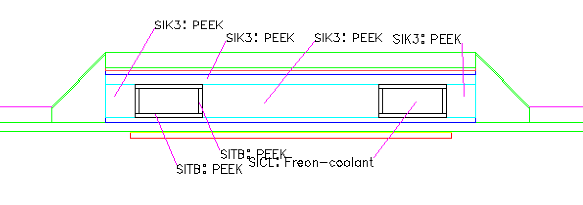
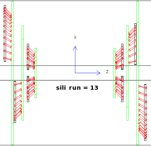
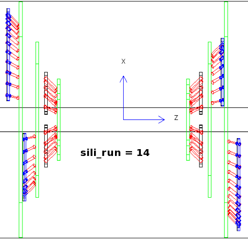
| (17) Before the start of Run 13, massive leaks were discovered in the VTX. The East VTX was removed, and the problem was traced to galvanic corrosion between the carbon foam core of the barrel 3 and 4 ladders and the aluminum cooling tubes embedded in the foam. The laders were rebuilt out of solid PEEK plastic. The top image (GEANT > next; dcut sj03 3 0 10 10 3.5 3.5) shows a cross section of a barrel-3 ladder. The Run 12,13 materials are K3 (=carbon foam), Aluminum for the cooling tubes, and Freon-coolant (=3M Novec 7200). The bottom image shows that this changes to PEEK when the run number (RHICRUN in pisa.kumac) is set to 14 or later. |
| ||||||
| (18) In run 16, the inside stripixel layer West was removed, and 2 carbon fiber tubes were put in place of ladders 1 and 8. In the picture, the top is a cross section at z=0, showing the carbon tubes in place of the B3W ladders. The bottom shows that the cooling manifold, representing a fair bit of (stainless steel) mass also has been removed. (committed to CVS 24 Feb 2017).
|
|
Hubert Van Hecke Last modified: Fri Feb 24 11:52:27 MST 2017