| The two halves of the VTX/FVTX are mounted on horizontal rails,
and as the two halves approach, ball shapes on one half meet the cones
and wedges on the other half, such that the halves become properly
aligned as they reach zero separation.
The figure shows the bottom two blocks of the kinematic mount on the (F)VTX support structure. If the opposite half, for example, is misaligned along the z-axis by 1 mm, the conical mount block will meet the opposing ball when the halves are 1 mm apart, and will force the halves to move at a 45° angle relative to each other in the horizontal plane, until Δz is zero when the two halves meet. |

| ||
| In the FVTX, the half-disks, here highlighted in green, meet
near the mid-plane. The support plane edges have small angles wrt the vertical.
In addition,
on each disk, wedges hang over the centerline, and fit
in space on the opposing half-disk. See
crossing the mid-plane The disks must approach each other along the exact relative z-coordinate as this final matchup occurs. The summary on the 'crossing' page shows that the largest overhang is 31mm for station 2. This is for the HDI. The number that matters is when the wedge's carbon backplane meets the opposing support disk edge, which is less, namely 0.95 mm. | 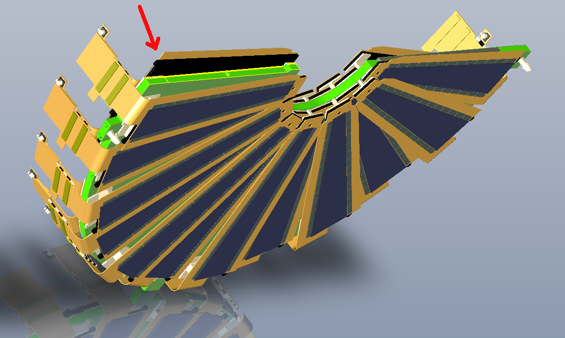
| ||
| A pair of objects like this serves as a kinematic mount up to where they touch, and then acts like a guide pin. | 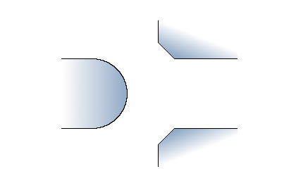
In the final assembly in the lab, the two halves rest on the same
rails on which they will sit in 1008. The rails are the only thing that
fixes the position. Note they sit on an ordinary table, possibly not
perfectly flat.
If the rails are slightly out-of-plane in the hall
relative to this setup in the lab, the tops of the two halves can end
up with a small sideways (z) relative displacement, which would be bad for the
FVTX.
| A guide pin at the very top of the frame would fix or at least indicate any such displacement.
|
Hubert Van Hecke Last modified: Mon Dec 22 16:57:57 MST 2014