Previous: ?   |   Index   |   Next: 3D fvtx model
FVTX test channel


The FVTX half-disks are cooled by fluid running through a channel that runs along the outer perimeter of the half-disk. Fluid enters through barbs that are perpendicular to the disk plane, and therefore the precise shape of the entry channel is important in order to minimize the impedance at these entry and exit points. Preliminary calculations show that the pressure drop across a half-disk would be 10 psi, which is right at the max pressure we (Don) will provide at the manifolds.

In order to convince ourselves that the flow will be adequate, we will build a test channel. It will have the inlet barbs and channel shape as the real half-disks, and will have the same length as the station 2,3,4 half-disk perimeter. Also, it will have the same distribution of holes alongside the channel, so we can see glue/leak problems early, if they exist.


Click for a bigger version-->

For incoming fluid, there was a sudden widening with sharp edges (fat green line and arrow. Even a sudden widening contributes to impedance. The red lines show a modified shape, with a sphere tangent to the barb's bottom exit rim, and a gentle (<8 degrees) flaring out to the right.


Click for a bigger version-->

The channel shape has been improved. Due to space limitations (the distance available between the barb and where the channel makes a turn), the slope is ~9 degrees. The channel will be milled with a 1/8-inch ball bit, and flare out later by 1/32" on each side to the 3/16" channe width.


Click for a bigger version-->

5 May 2010: Concerns about the strength of the barb attachment → increase the barb foot size.

on a disk


Click for a bigger version-->

July 2010: A test channel was fabricated by Eric Anderson with the input and output barbs shaped to minimize impedance to fluid flow. Since most of the flow impedance is at the entry and exit points, the rest of the chanel is just a 20 cm straight section, having the proper cross section.

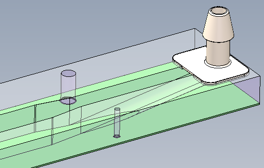
The test setup consisted of a CO2 gas bottle, a pressure reducer and precision pressure gauge, followed by a 2-liter water reservoir, marked at 250cc intervals, followed by the test channel and a drain. Time (in seconds) was marked as the water level fell past these marks. The nominal operating pressure drop is 20 psi.

Raw data, 2 runs per pressure setting:
     10 psi       20 psi        30 psi        40 psi
  ---------     ---------     ---------     ---------
                                    :18     :58   :15
  :12           :08   :10     :18   :25     :04   :21
  :18   :41     :17   :18     :26   :32     :10   :28
  :29   :52     :25   :26     :32   :38     :16   :34
  :39   :04     :33   :35     :39   :45     :22   :40
  :51   :17     :40   :43     :46   :52     :29   :46
  :02   :28     :49   :51     :53   :58     :35   :52
  :14   :39     :56   :59     :58   :05     :41      
  ---------     ---------     ---------     ---------
 21.8 cc/sec   29.8 cc/sec   37.4 cc/sec   40.6 cc/sec
There is a weak dependence on pressure, with

flow ~= ( 15.5 + 0.63*psi ) cc/sec

(plot to follow)

In the 2007 Hytec design report, page 40, the flow rate is set at 14cc/sec for #M HFE7200. for a estimated pressure drop of 1.7 psi per half-disk, including barbs. This is based on a power dissipation of 100 uW/channnel.


Apr, Jul 2010 HvH