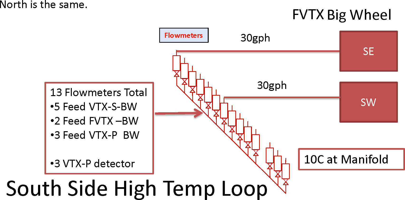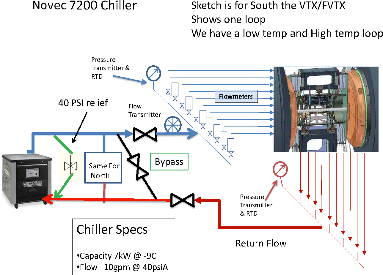
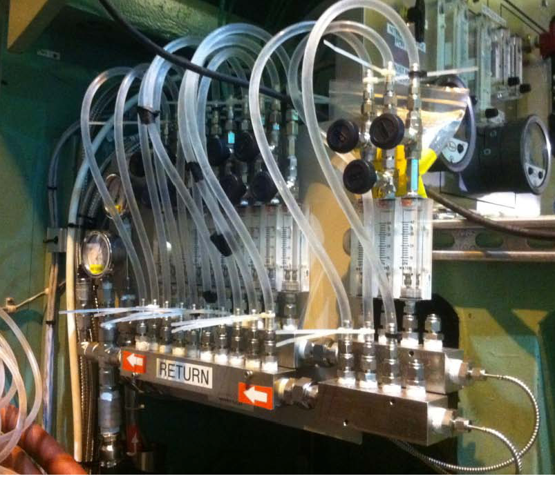
The pressure drop through the flow meters is about 1psi, and the drop from there to the top of the VTX/FVTX (the input side) is about 7 psi. The output lines have 1/4" ID.
Temperatures from the
OPC server:
FVTX coolant in
FVTX coolant out
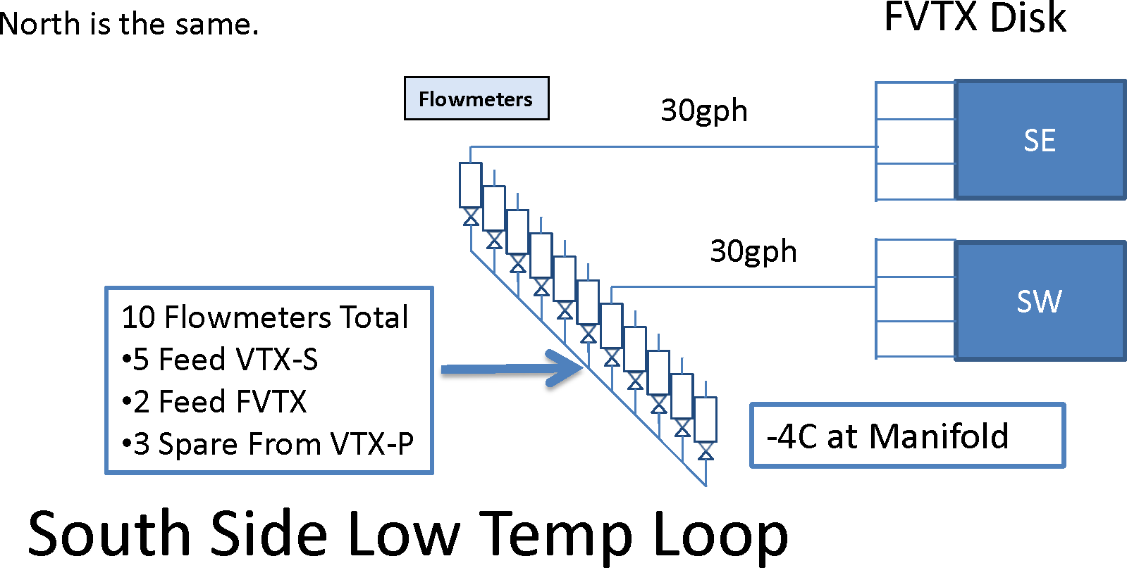
- 5 strip cooling
- 2 FVTX cooling
- 3 free

(to be modified 14 Mar 2012)
[Thermocouples not yet readable]
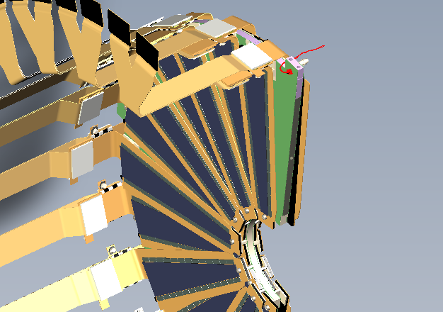
| The cooling channel runs through the outer perimeter of the half-disks. | 
|
- xx Big wheels
- xx VTX pads
- xx free