The ROC II GUI is used to download the wedges,
establish fiber optic communication between the ROC and FEM boards, and
collect data. Some of the basic DAQ buttons are described here, in the
order in which they are generally
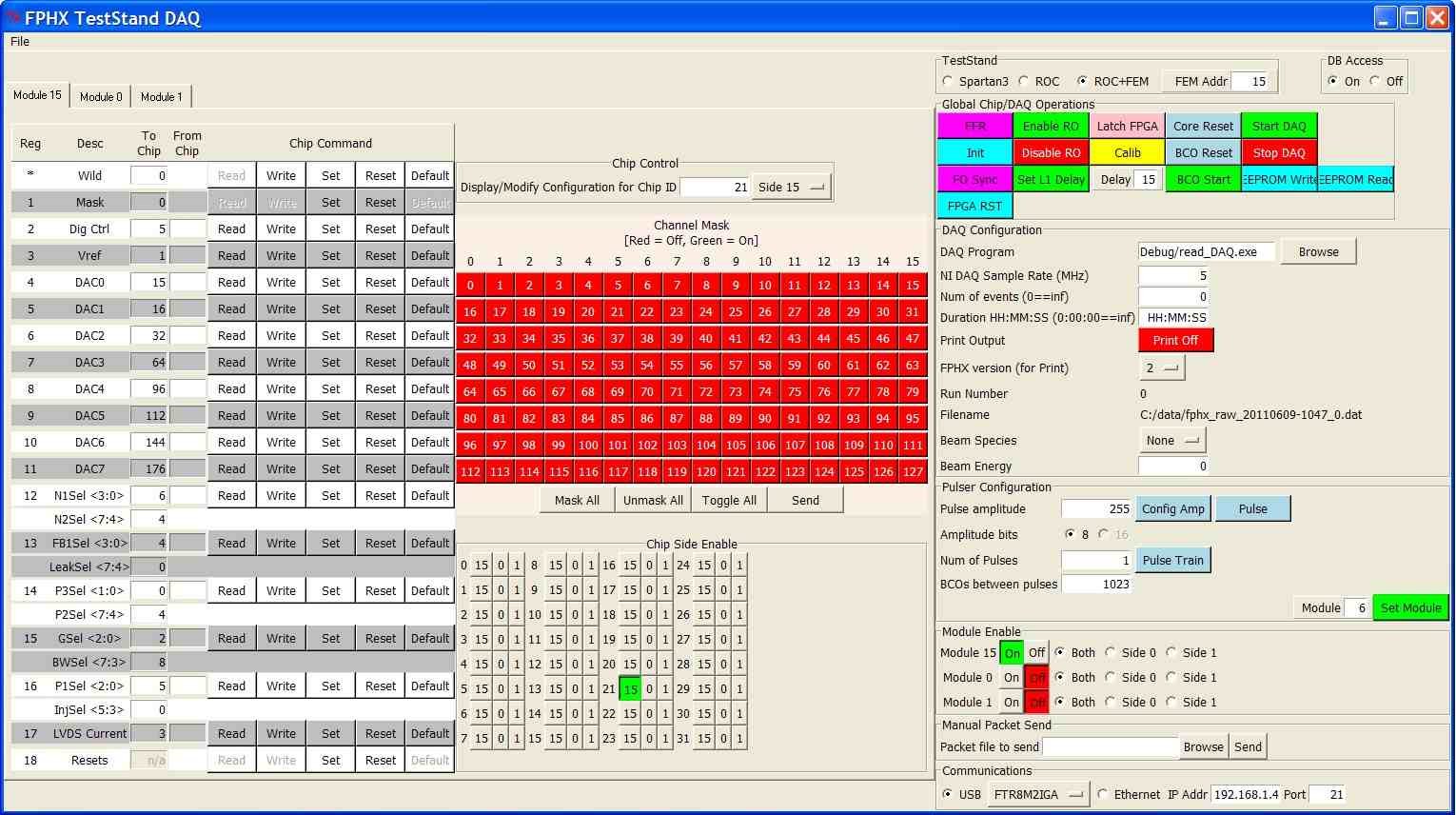
pushed when collecting data (and the buttons can be found in the image
below, primarily in the upper right-hand corner):
- FPGA Reset: This issues a reset to the FPGAs on the FEM,
FEM Interface and ROC boards. It should be issued
after you first power up, and we generally issue one before data
collection.
- FO Sync: This generates the fiber optic synchronization
sequence on the slow control fiber. If the
synchronization has been successfully achieved in both directions
then the top, left-most LED on the FEM will
light up. If it isn't achieved, just hit the button again until
sync is achieved.
- FFR: This used to be the general reset button but now it
just issues a fire-fighter reset to the FPHX
chips. This should be issued after power-up of a wedge and before
sending an INIT command.
- INIT: Download parameters to FPHX chips. This needs to be
issued after FFR.
- Enable RO: This sends and enable readout command to the
FPHX chips. It is necessary to hit this after
an INIT to get the data words to come out of the FPHX chips.
- Latch FPGA: This LATCH command serves two purposes - first,
it initiates the fiber optic synchronization
command to the ROC data fibers. If synchronization is achieved,
then all 8 lights for each fiber that is connected
to the FEM should become lit on the FEM front panel (3rd and 4th
rows of LEDs go with the bottom fiber on the FEM,
5th and 6th rows go with the top fiber on the FEM). Second, the
LATCH readies the ROC data FPGAs for data collection.
- Start DAQ This readies the NI for data collection.
- BCO Start This command is needed to synchronize the
beam-clock counters on the FPHX chips and the FEM.
It simultaneously issues a start counter command to the FEM and
down to the FPHX chips. The result is that the
two will be counting in sequence but it does not cause the
BCO clock for a calibration, for instance, to be
on the same clock each time you run calibration.
- Calib: Issue a calibration command to the ROC board. After
the command is received, the ROC will initiate
a full calibration sequence for the chips.
- Set Module: This must be set each time you want to change
the module that is being calibrated, but does not
need to be sent again for subsequent runs that are to use the same
module. This button is a bit of a misnomer right now
because it actually selects one of 8 possible "sides" to calibrate
in a phi slice. "0" corresponds to station 0, side
0, "1"=station 0, side 1, "2"=station 1, side 0, etc. This should
be changed to specify the phi slice, the module, and
side to be calibrated, and allow for multiple modules to calibrate
at once.
(click the image to enlarge)
|