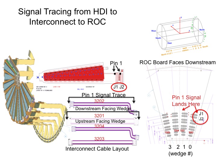
Wedge-->Extension Cable-->ROC Connections
The wedge to extension cable to ROC connections, and numbering schemes, are illustrated here:
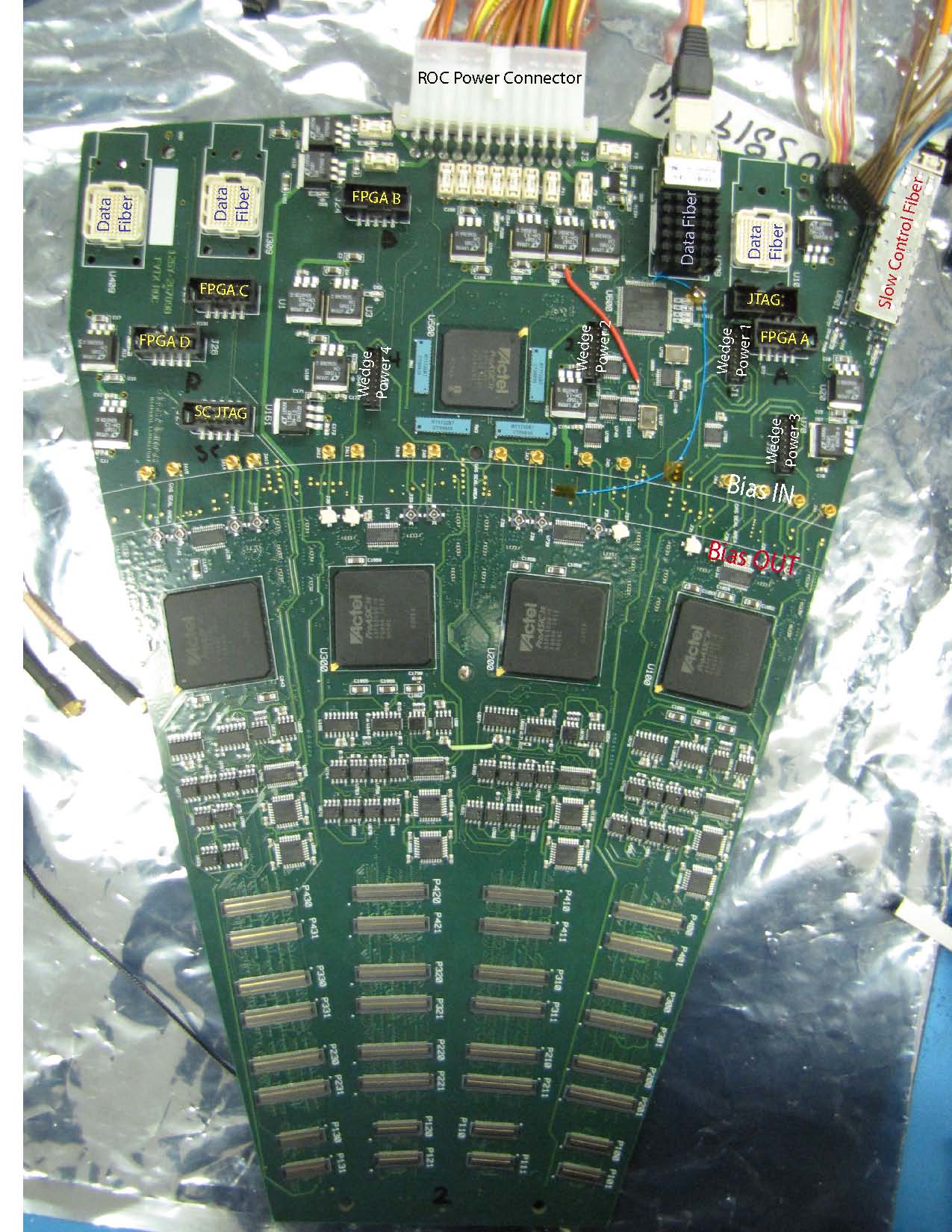
ROC II Board connections:
The various connections to the ROC board are illustrated in the photo below with a brief description here:
- The main ROC power connector is located at the top center of the
ROC board and supplies 2.5V and 3.3V to the four data FPGAs, the slow
control FPGA, and the JTAG FPGA. 3.3V also goes to the clock
distribution circuit. 5V goes to the calibration circuits. The pinout
of the power connector can be found
here
- Slow Control Fiber : The slow control fiber is located on the top
right of the board and runs from the ROC board to the FEM board, which
sits in the VME crate.
- BCO Clock and Clock Start: The bco clock and clock start come in
on an 8-pin connector located right next to the slow control fiber on
the upper right portion of the board. These signals come from the clock
distribution board, which receives the signals from the FEM Interface
board, located in the counting house.
- Data Fibers Four data fiber bundles (two on the top-right side of
the board and two on the top-left side of the board) connect to two FEM
boards, with one fiber bundle associated with each ROC data FPGA. The
FPGAs are designated as A,B,C,D running from right to left when the
board is viewed from above (as below).
- Wedge LV: The wedge analog and digital voltages are supplied by
four 16-pin connectors on the top-half of the ROC, labeled as Wedge
Power 1, Wedge Power 2, Wedge Power 3, Wedge Power 4. Each connector
supplies the analog and digital voltage to one station, with the four
station positions noted in the photo below.
- Wedge Bias: Wedge bias is supplied separately for each of the 16
wedges that are connected to the ROC. The bias voltage comes in on an
MMCX connector, above the gas seal, and goes out the the wedge via an
hirose cable which is connected to the ROC board below the gas seal.
The bias connectors, from right to left will supply voltage for station
0-wedge 0, station 1-wedge 0, station 2-wedge 0, station 3-wedge 0, then
station 0-wedge 1, etc.
- Wedge Connection Sixteen wedges will be connected to a ROC board.
The right-most connectors on the board are designated for "wedge 0",
stations 0-3, followed by "wedge 1", "wedge 2", "wedge 3".
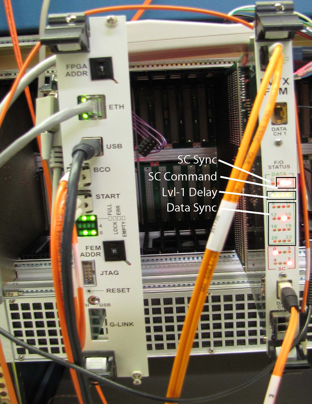
FEM, FEM Interface Board connections:
The various connections to the FEM and FEM Interface boards are illustrated
in the photo below with a brief description here:
- FEM Interface: The FEM Interface connections, moving from the
top of the board to the bottom are:
- FPGA Address This determines which FPGA on the ROC you
will program if you are programming remotely via the FEM Interface
board. The FPGAs are SC=1, Data FPGA A = 2, Data FPGA B = 3... (need to
check this)
- ETH Ethernet slow control interface, connects to the
PC. Slow Controls come either via ethernet or USB, depending on which
is selected from the user GUI.
- USB USB slow control interface, connects to the PC.
- BCO BCO fiber, which goes to the clock distribution board.
- START Start fiber, which also goes to the clock distribution board.
- LEDs LED outout monitoring from the FEM Interface.
- FEM Addr
- JTAG JTAG connector which is used if you are remotely programming
the ROC FPGAs.
- Reset Recessed button which allows a hard reset of the FEM Interface
board. This reset is also
propagated to the FEM board(s).
- G-LINK Interface to the GLINK board that is on the FEM Interface.
This is where the BCO clock,
T&FC come in. If no G-LINK board is present, a BCO-CLK must be alternately
supplied by a Spartan-3 board.
FEM Board: The FEM connections, moving from the top of the board to the bottom are:
- SC Slow control fiber, connects to the ROC board on the top right corner.
- DATA CH1 Data fiber 1 from a ROC board. Each FEM board receives 2 data
fibers from a ROC board.
- LEDs FEM monitoring LEDs. Some are labeled in the
photo: top left is lit if slow control fiber synchronization is achieved
(should be after you issue a "FO SYNC" from the gui". Three LEDs
indicate the slow control command that was issued. Four LEDs indicate
the current LVL-1 delay. 16 LEDs indicate the synchronization state for
the two data fibers coming in (synchronization should be achieved after
issuing a LATCH command). The bottom 8 LEDs are from the slow control
portion of the FEM and depend on the current state of the slow control
FEM coding.
- DATA CH2 Second data fiber connection, coming from the ROC board.
|