Clock board connection 2012
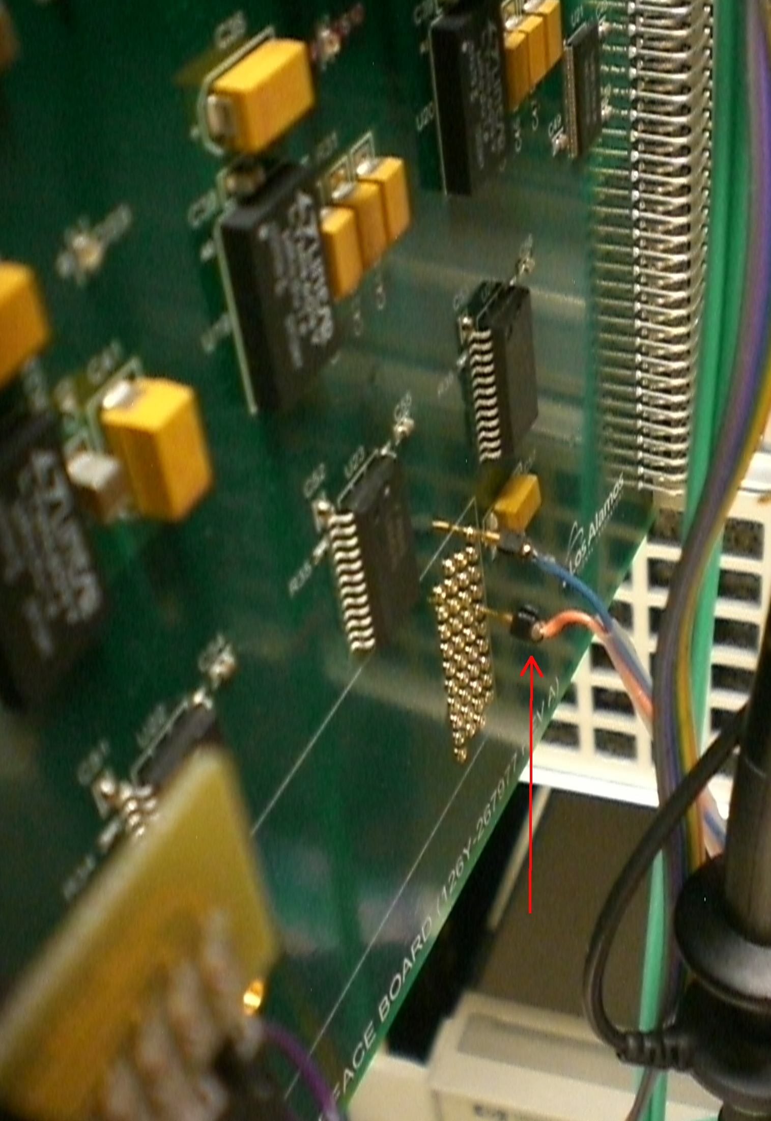
| This is the setup as seen in the LANL lab, Aug 2012.
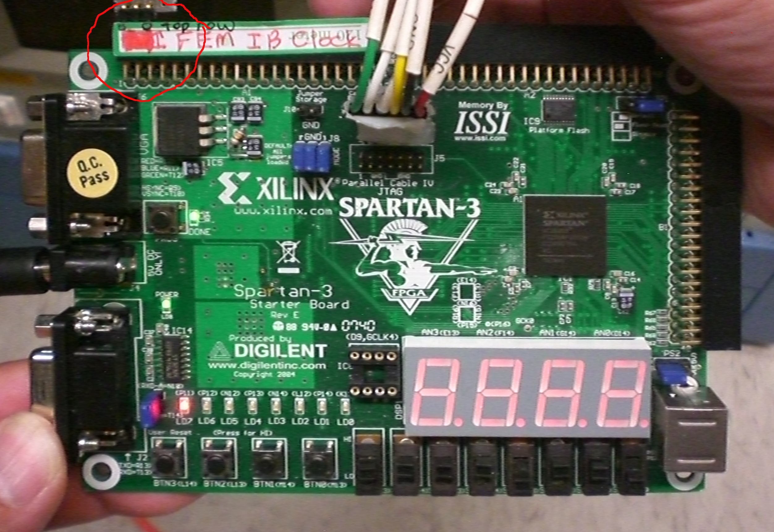
On this Spartan-3 clock board, the clock signal goes to pin 5 and the ground goes to pin 1 of connector A1, circled in the picture. Pins are numbered as follows:
2 4 6 ....
1 3 5 ....
with the odd numbered pins ending out on the top row of the header pins.
|
Hubert Van Hecke Last modified: Wed Aug 8 16:20:02 MDT 2012