FEM JTAG cables
| The JTAG header on the FEM board is a 6-pin .1" header. We use a regular 14-pin connector, of which only the 6 pins on the bottom left are used. The connector needs to be attached at an angle in order that the 6-lead ribbon can run flat. | 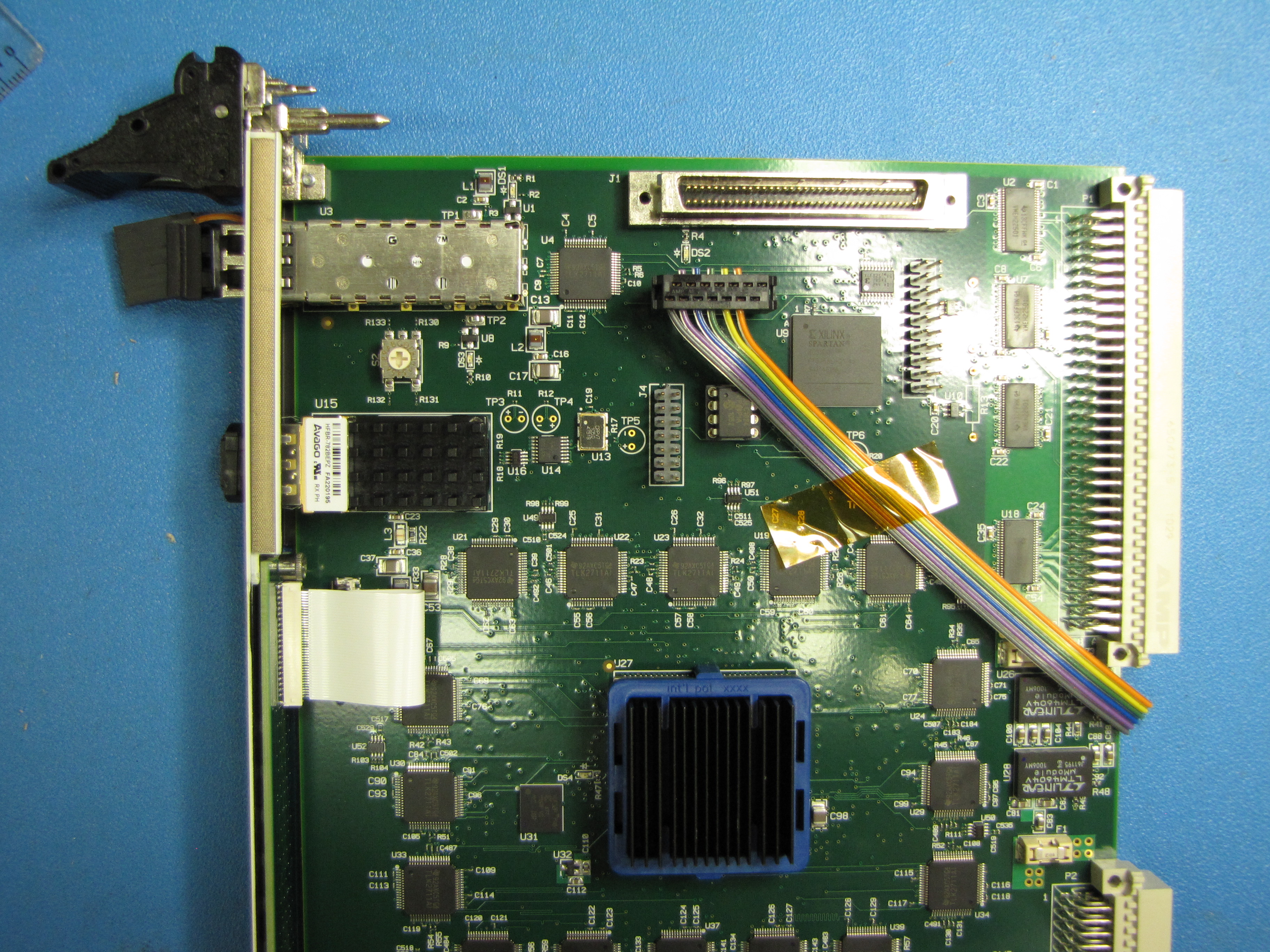
|
| A simple jig is used to hold the conector at an angle, and it has a channel to hold the ribbon in place. Split the end of the ribbon, lay the wires in the connector, snap the top in place and squeeze the connector in a vise. | 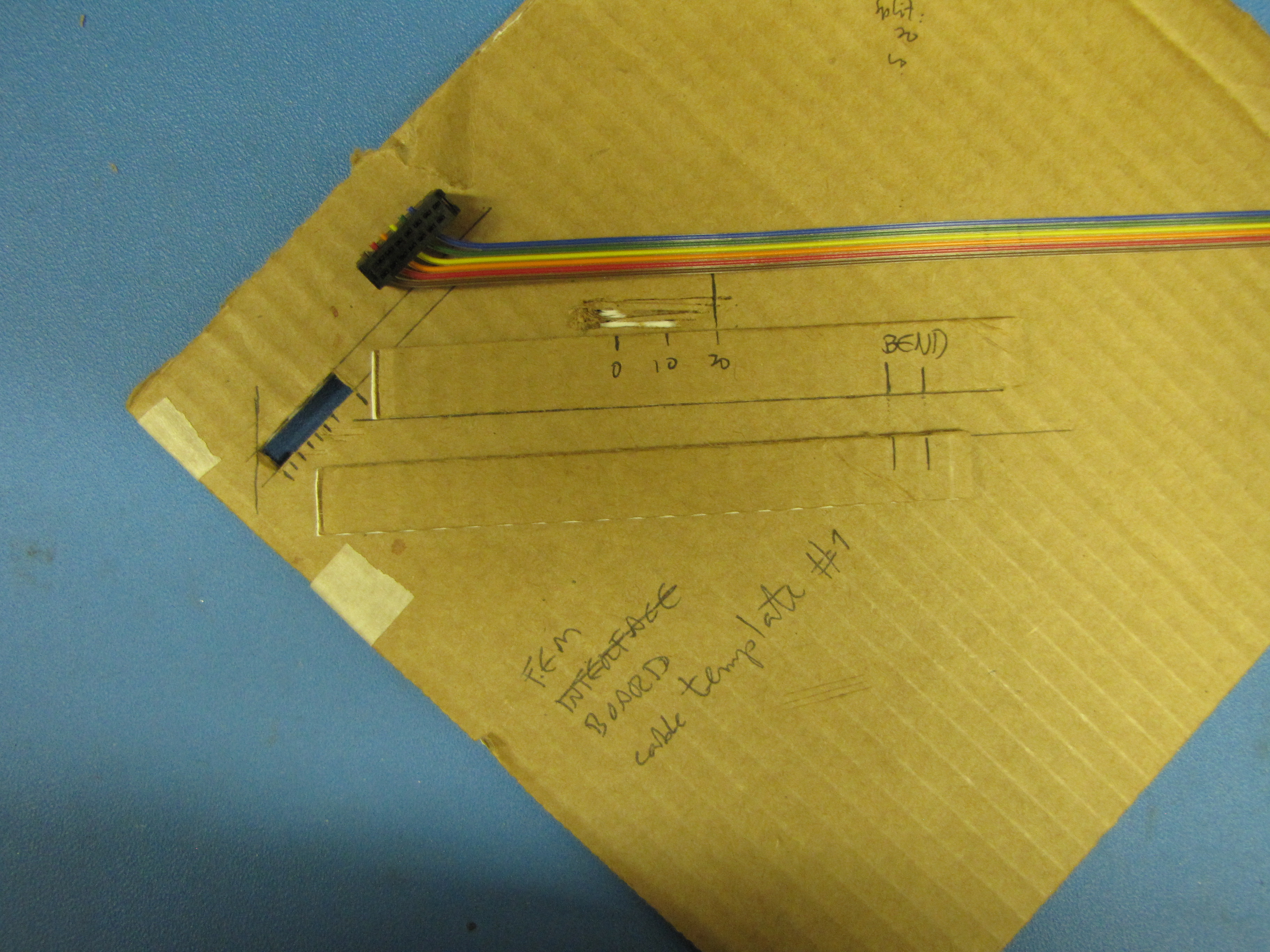
|
| On the other side the cable lays flat, and emerges trough the top hole in the front panel made for the optical fiber connector. A small 6-pin connector is mounted, again at an angle since there is no clearance between the card handles. This one is small enough to fit through the hole. | 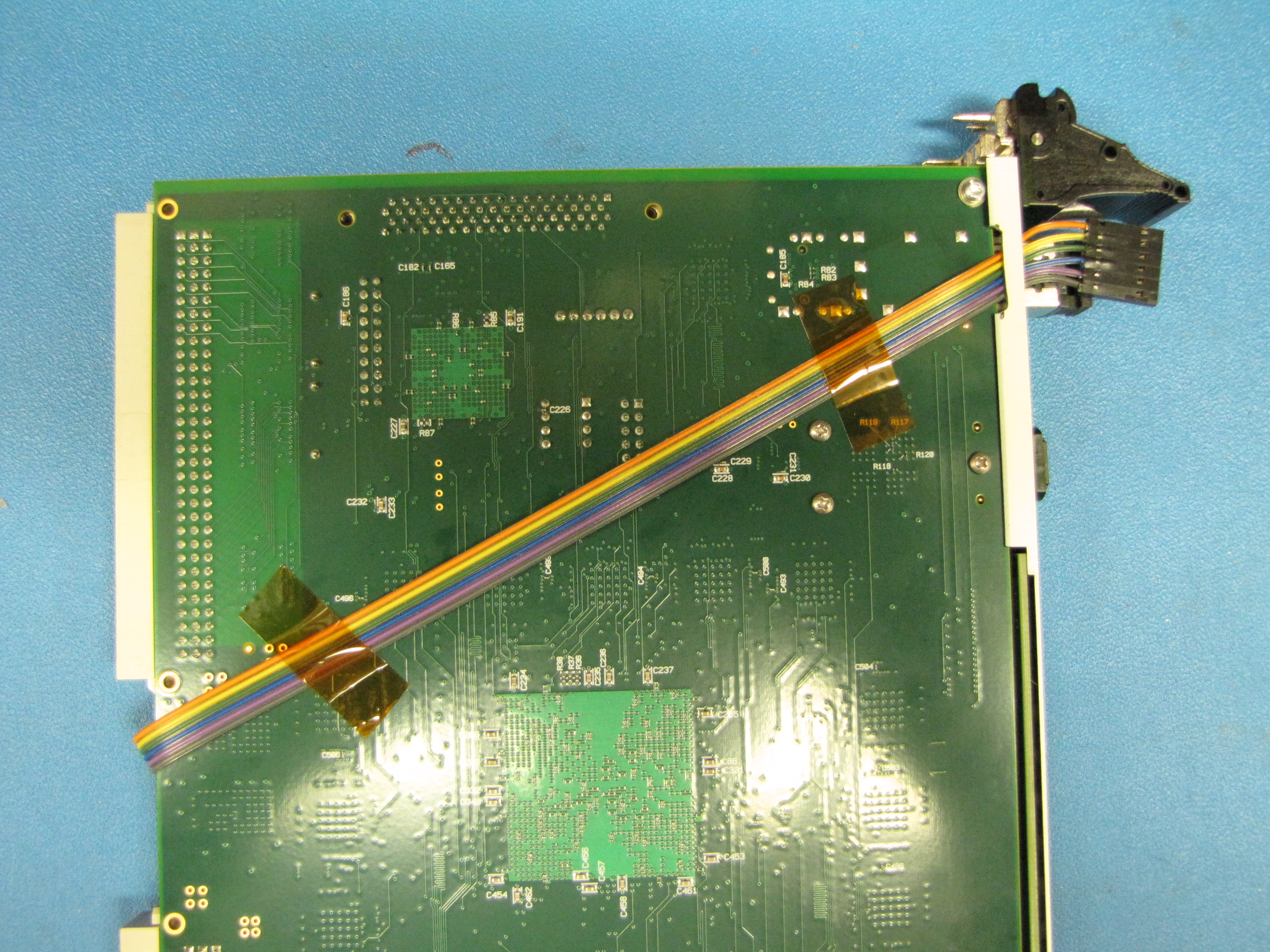
|
| A similar jig to hold the ribbon and connector, split the ends and do a final test of the cable. | 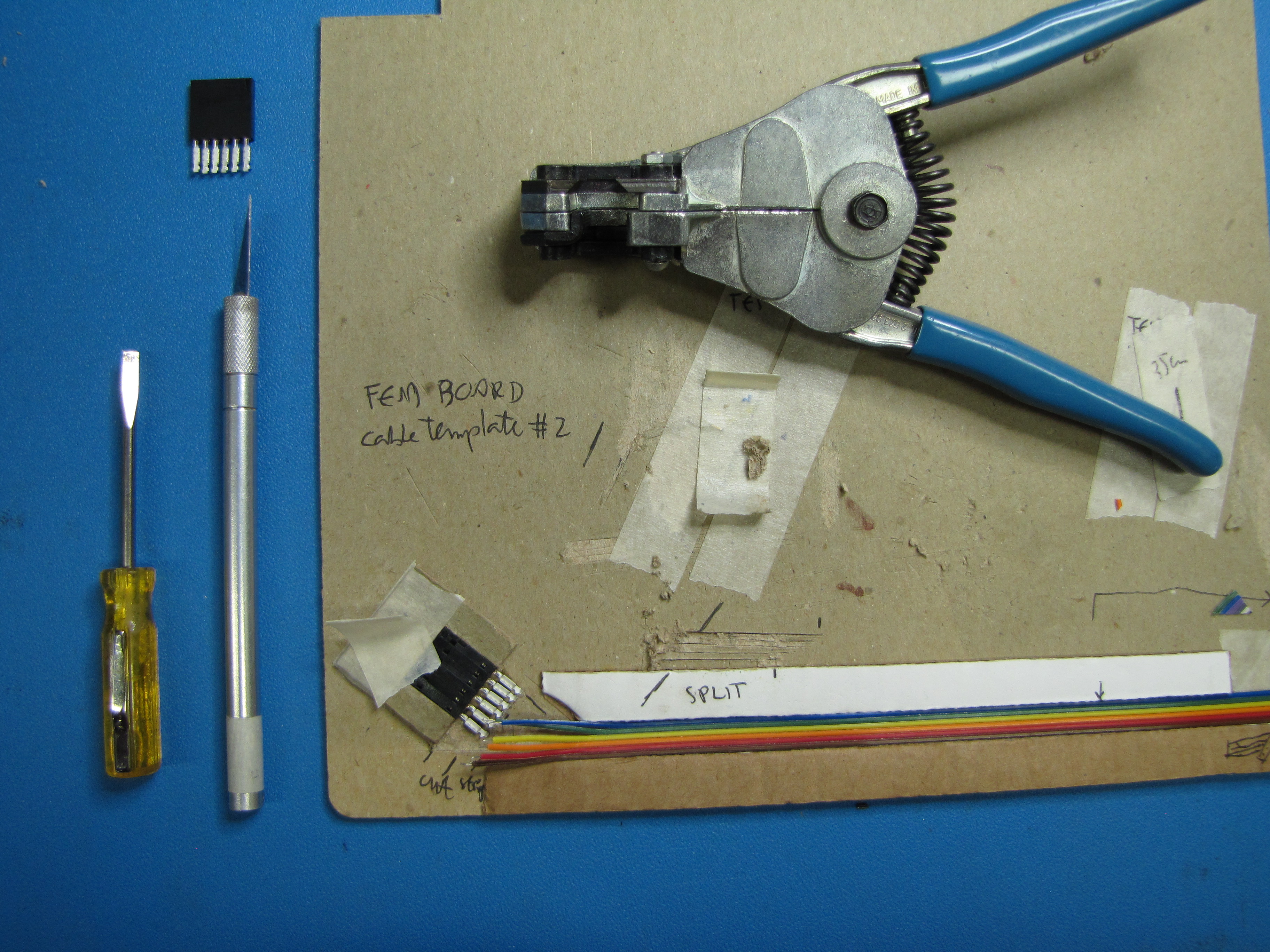
|