| The transceivers are held in a cage which is soldered
to the board. There are 8 solder points (A),
4 are indicated. The top
cover of this cage clips over the top of this bottom U-shaper part
and is soldered only in 3 places in the back (B).
The walls of the cage have tongues which are folded over the back of the cage
after the top is put on. Here (D) they are bent back
when the top was lifted up and off.
The triangular hole (C) is where a latch on the
underside of the transceiver catches.
| 
|
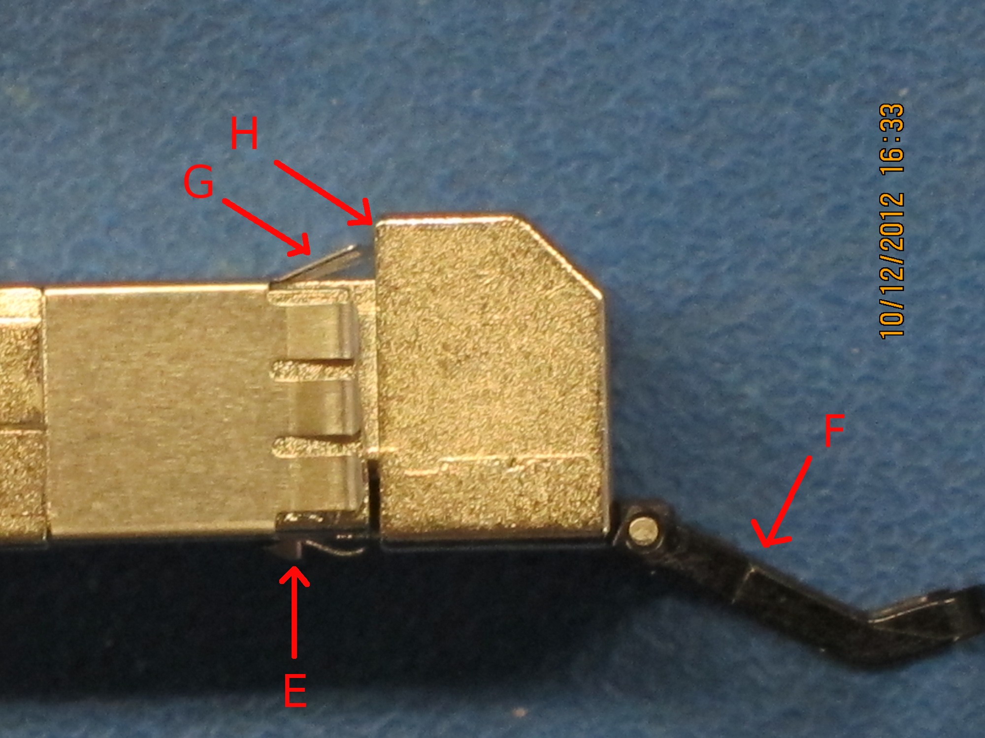
| This is the underside of the transceiver.
(E) is the latch that catches in triangular hole
(C). All the black plastic parts
(F) are part of the latch release mechanism.
| 
|
| Side view of the transceiver. (E) is the
latch and (F) is the latch release.
The only (proper) way to get a transceiver out of a cage is by using
the latch release.
If you have managed to remove a transceiver without
exclusively pulling on the latch release (F),
you have lifted the transceiver
up high enough to get the latch (E) up and out
of hole (C).
(G) are flexible fins (also visible on the side here)
that ensure ground contact between the transceiver and the cage.
Normally, the top of the cage is lower than (H).
| 
|
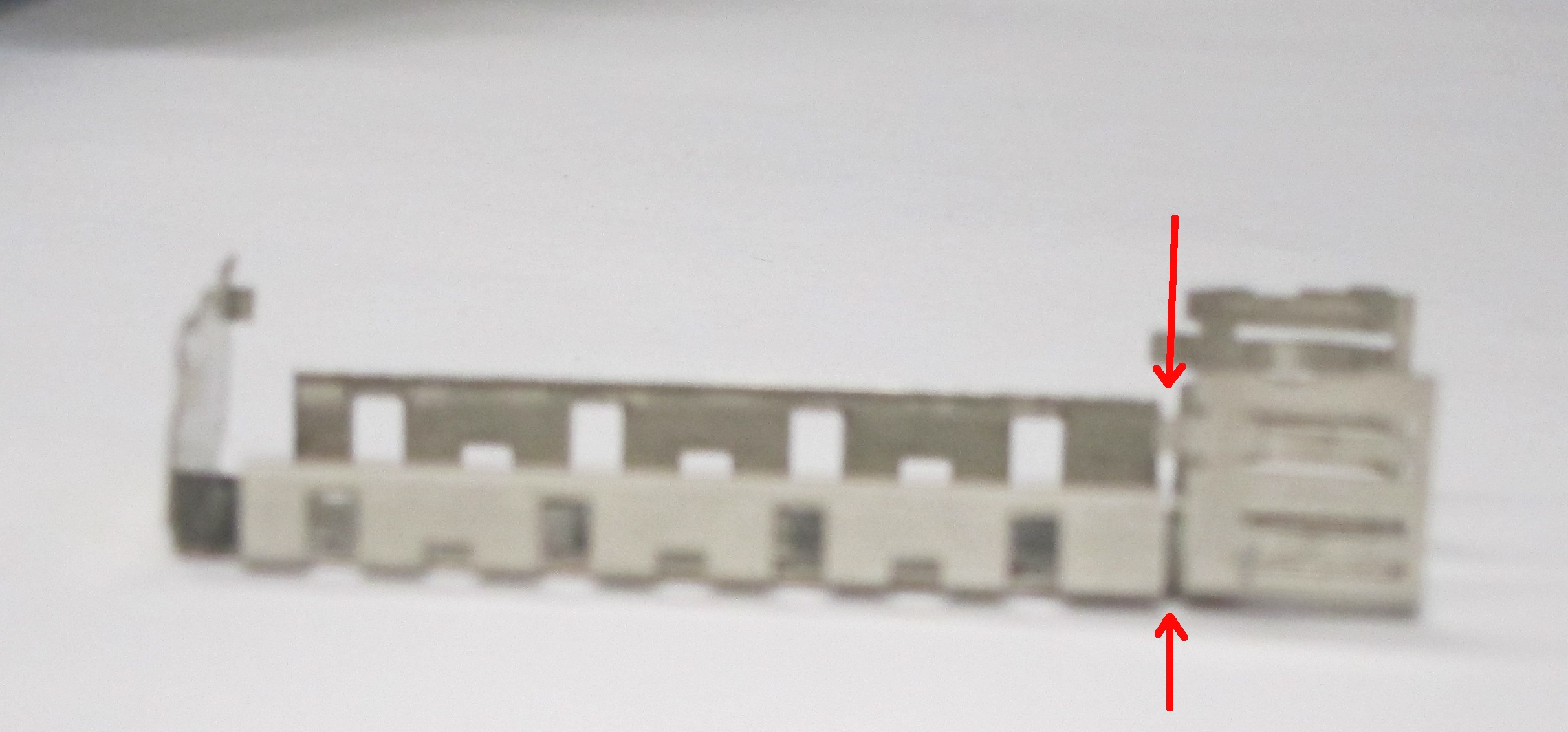
| This is the top cover of the cage, shown upside-down. Note the
sidewalls are not continuous front-to-back. This allows the taller front part
to bend up with almost no force.
On some of the cages, this front part is not secured, and the grounding fins
(G) can push it up.
| 
|
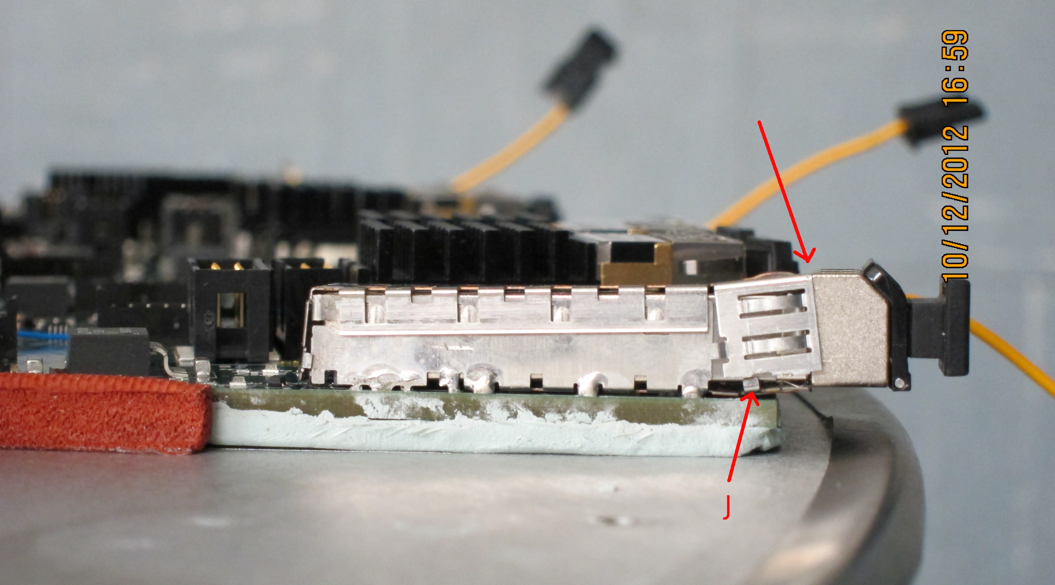
| This can be seen on this one. Note tab
(J). On some cages this is soldered to the bottom
part of the cage, so that the cage is solid and the tranceiver cannot be
lifted.
If the front part of the cage is lifted like this, the edge of the transceiver
is no longer stopped by the top edge of the cage, and can be pushed
in deeper than intended.
I believe this is what is happening when damage occurs.
| 
|
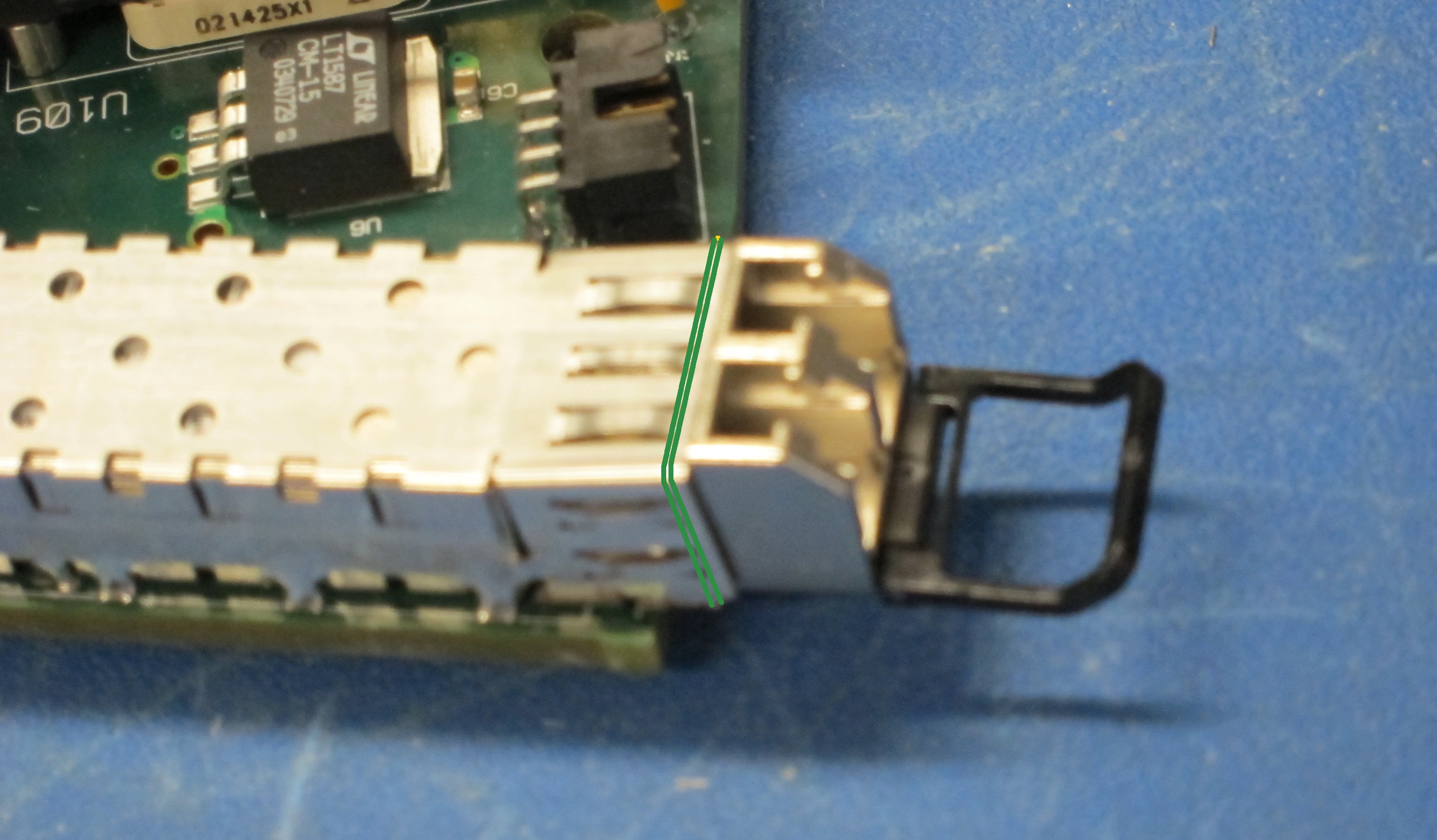
| One way to prevent this
is to tie down the front part of the cage in all cases where it is not
held down by the solder tab (J). We will wrap it with
cotton thread and secure this with white glue.
| 
|
| Two alignment holes catch two pins on the underside of the
connector. Thus if a force is applied from the front, the connector cannot
slide back, but has to lift up first. So first the front pads rip off
vertically, and then the back pads bend and peel off.
| 
|
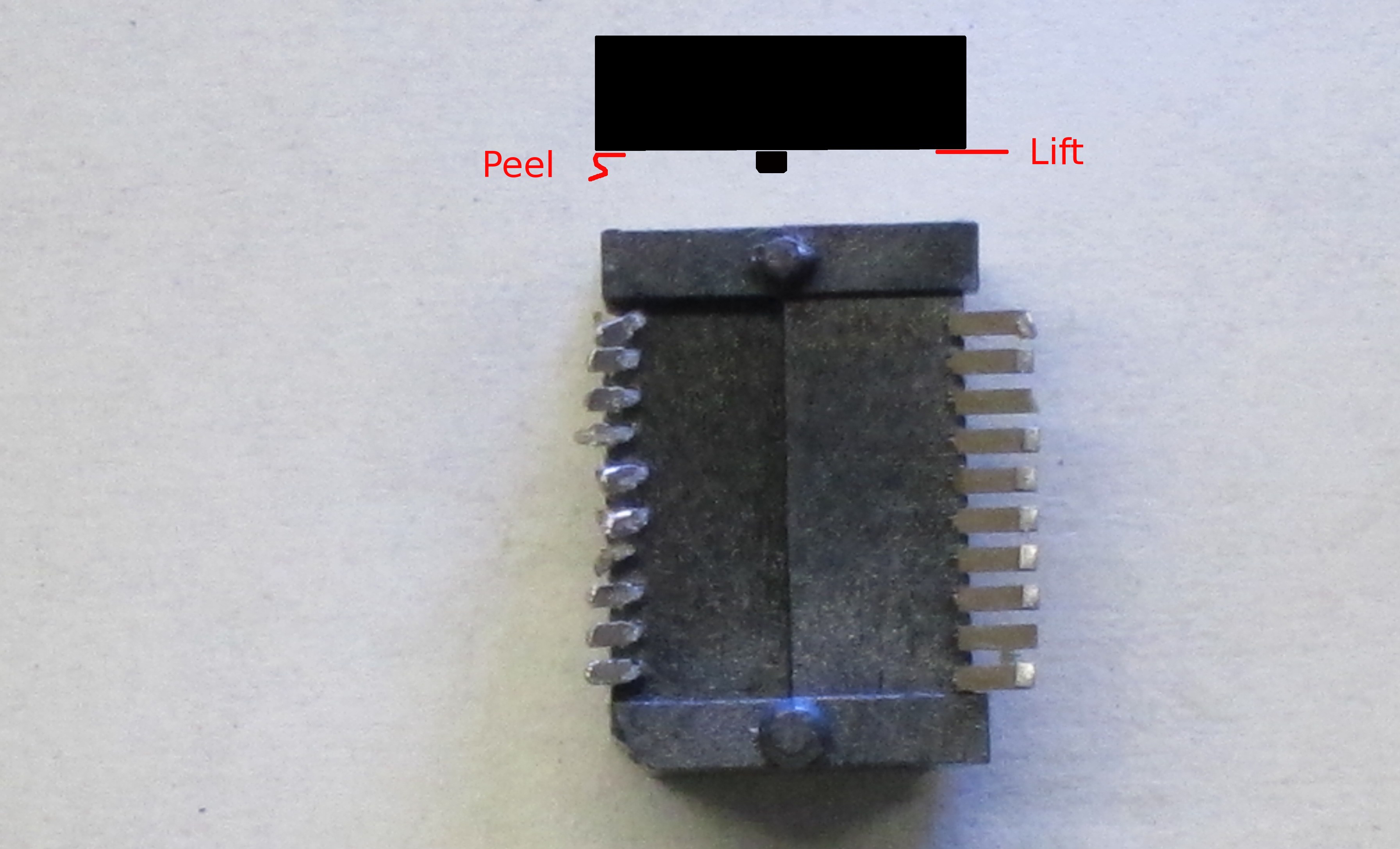
| This can be seen here: The pads on the right are lifted clean off,
and the ones on the left are folded over as they peeled off.
| 
|