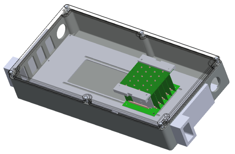
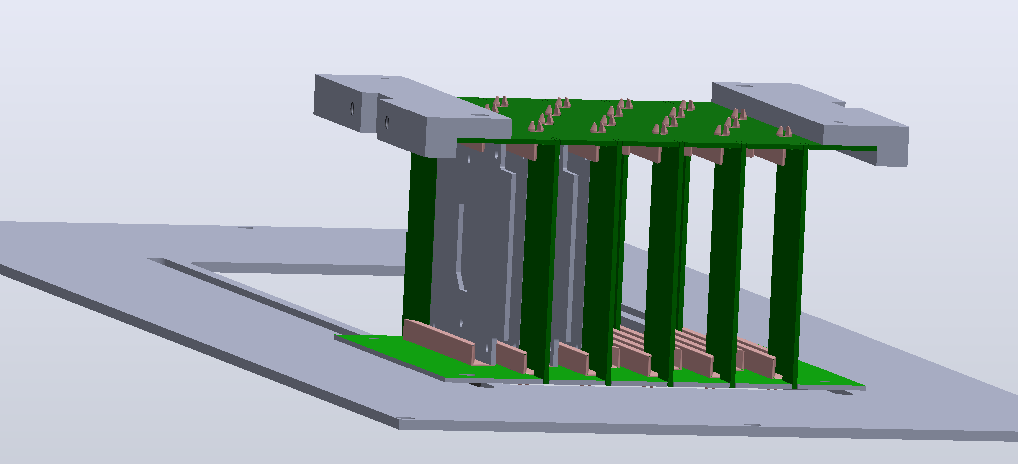
- This is the single-chip PC board, 70×70mm plus connector space.
It slides into a slot.
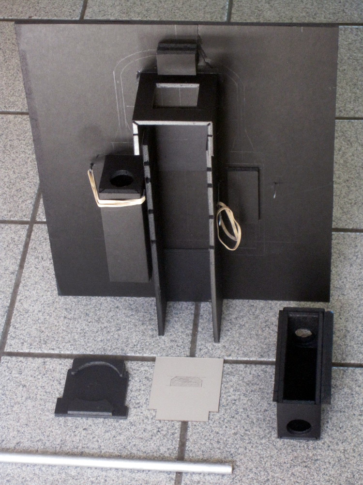
- This tray holds the source. The source is a 2" cylinder. The tray
slides out, and can be positioned at different heights.
- These are the boxes that hold the PMTs. On the left you can see the
profile drawn on the back board of the top of the tube, and the light
guide.
Dismount the box, thread the cables through both holes, and slide the
PMT into place. The bottom of the tube fits into a cutout at the bottom.
The fit is supposed to be snug. If it is too tight, rub the edge of
the hole with the stick (6) - this will open it up a little.
(The boxes are not quite identical left and right).
- After the tube/lightguide/scintillator is fit into the holder box,
slide it over the alignment block 4, and down until it clicks.
Secure it with the two rubber bands.
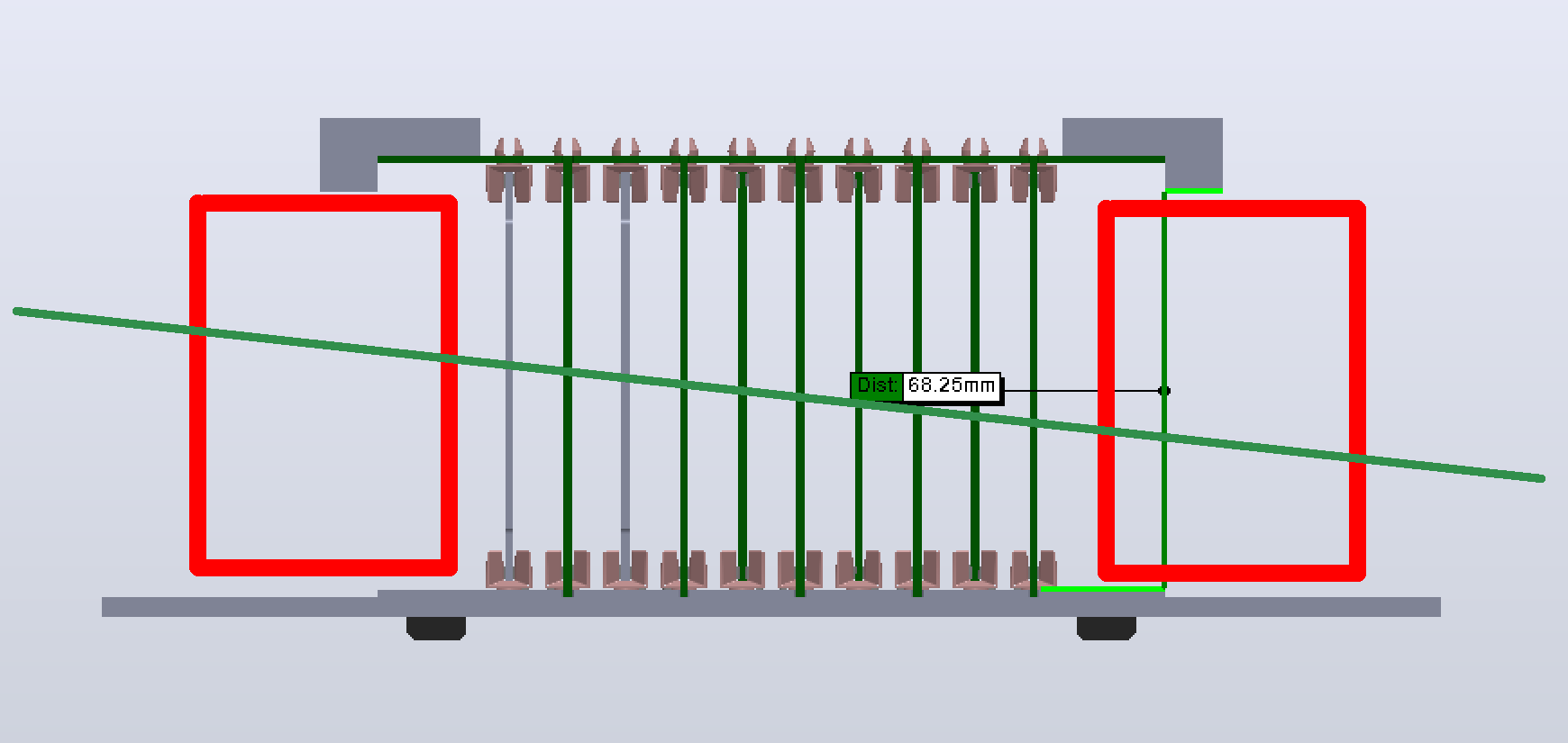
- This block ensures that the scintillator squares are aligned with
centerline of the source, MAPS chip and PMTs, which runs 35mm from the
back board.
I would take the stainless box, remove the front panels and the inside plates,
and attach this board against the back plane.
| 
|