Notes on Installation
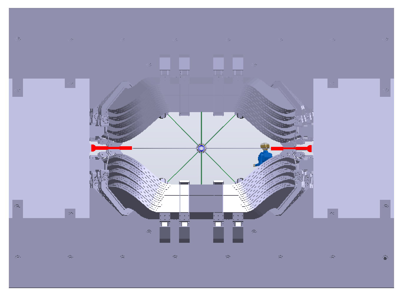
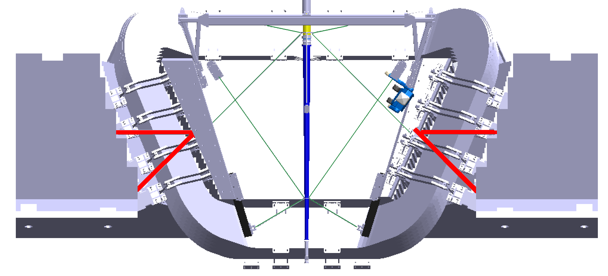
| (1) Isometric front view (right) and top view (below), from this EASM file. The diagonal wires (green) of the spider attach the front of the beampipe to points near the front and the back of the magnet (both top and bottom). The horizontal and vertical wires attach the back of the beam pipe to points in the center (z) plane, as well as to the back. In red is a frame where the horizontal wires attach.
| 
|
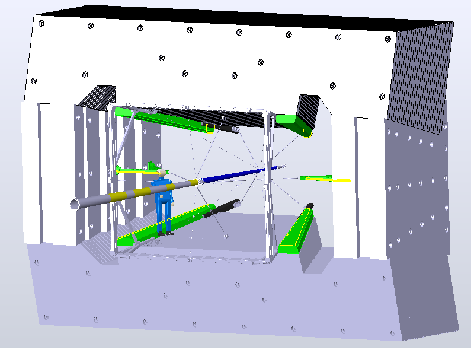
| (2) There are 4 bars (green), which appear to be part of the magnet poles. These would make good attachment surfaces. However, the various spider frames and points are not mounted from these bars. Are we allowed to mount to these bars? |
|
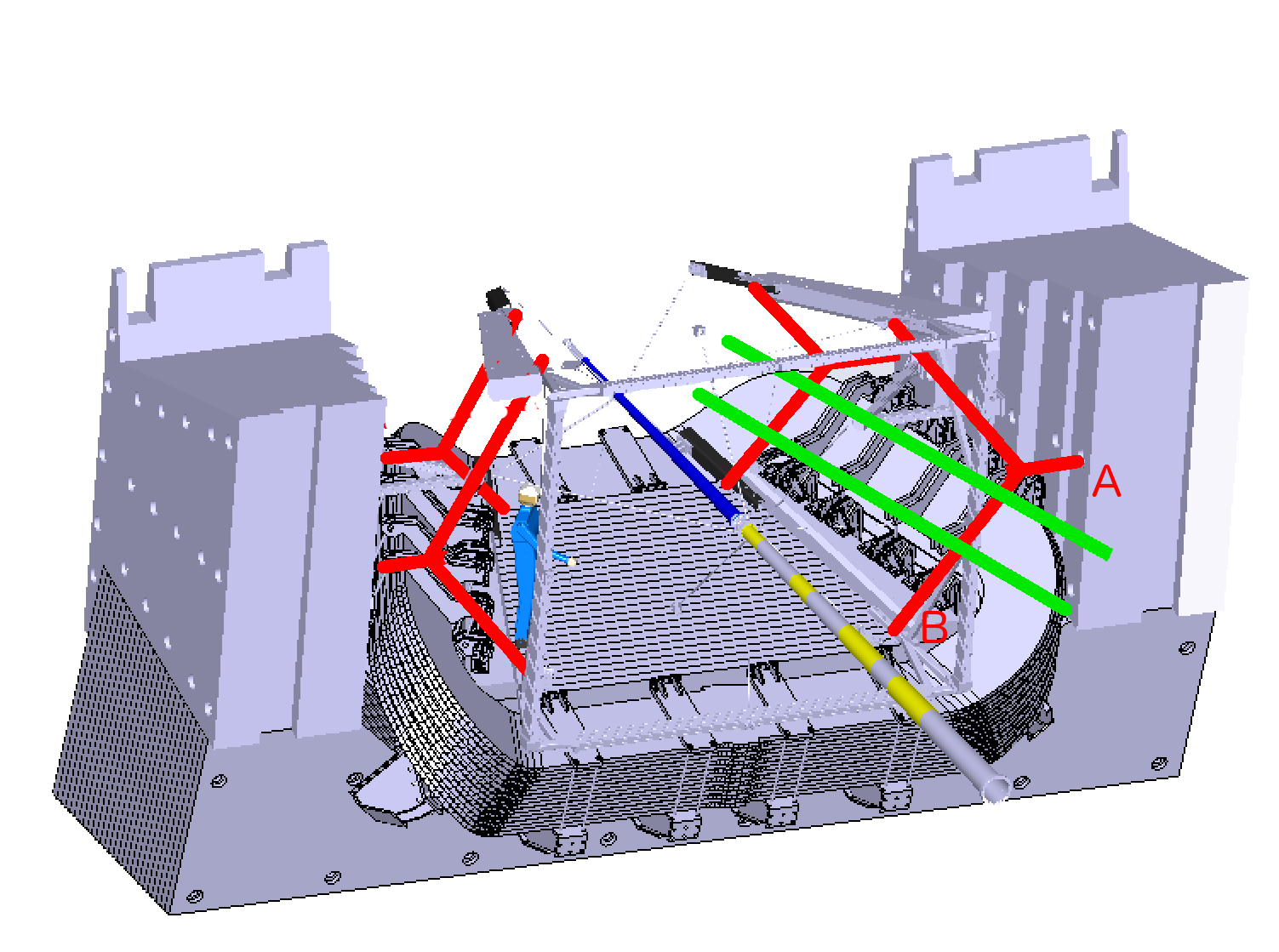
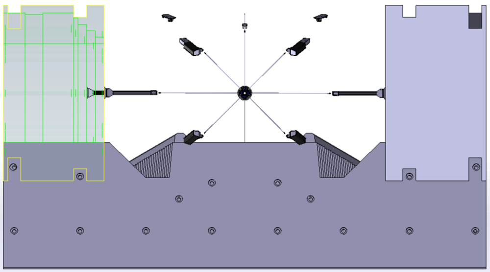
| (3) Top of the iron removed for clarity. In red are Y-shaped brackets which are anchored
in three points: points A are on the vertical walls, on the horizontal
center plane. Points B are near where the anchor points for the beam
pipe spider are. The angled sections are parallel to the magnet coil face.
| 
|
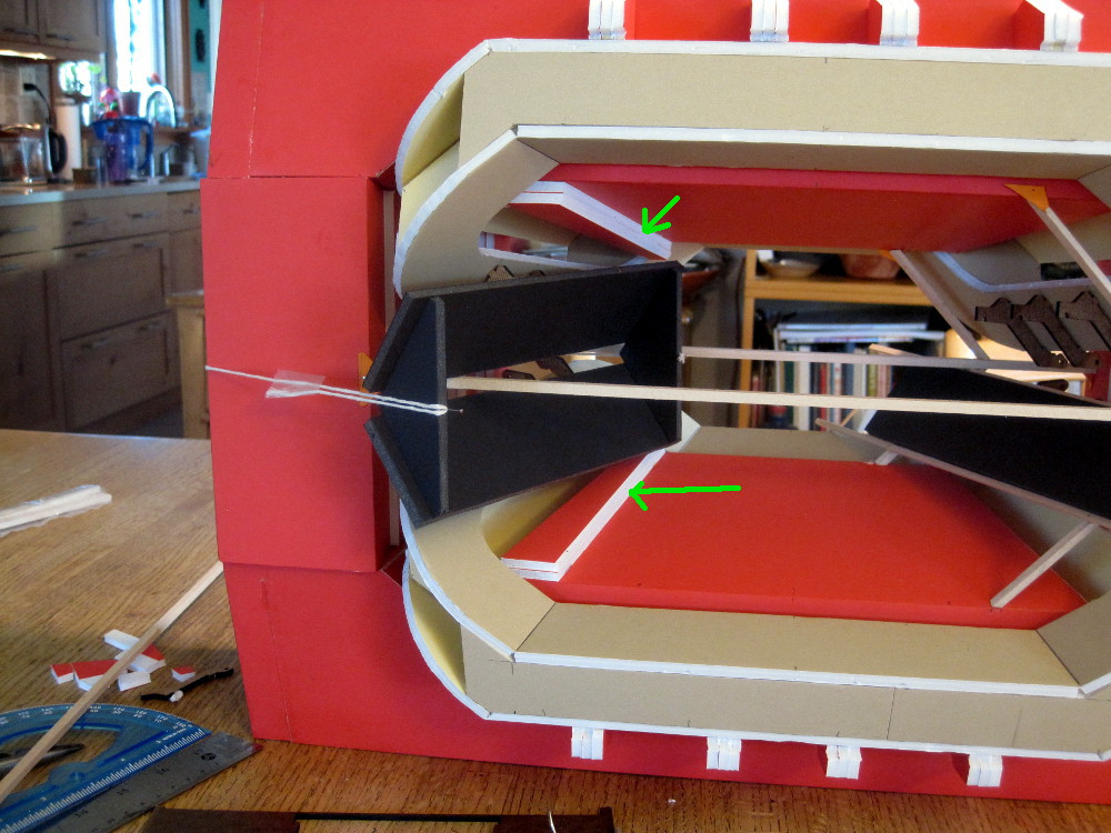
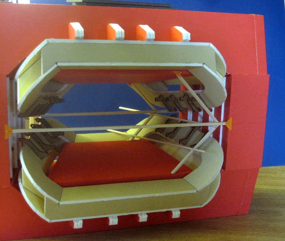
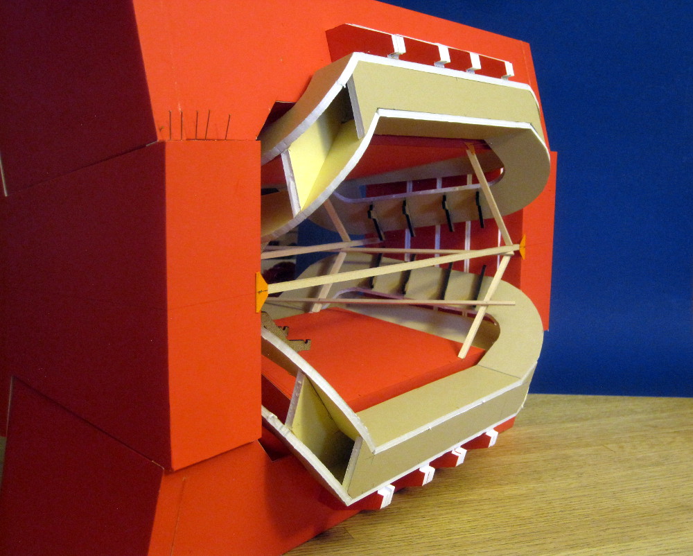
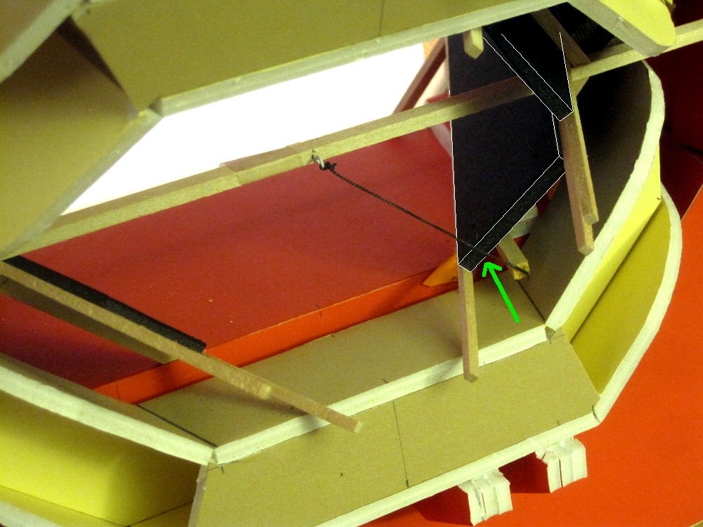
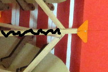
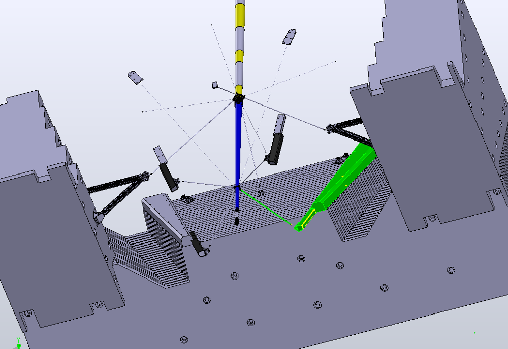
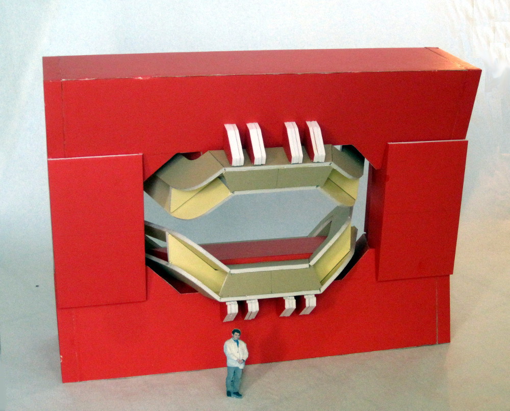
| (4) Using the 1:20 scale model: The way I placed the chambers is by first joining the 1×4m chambers together with a ~20cm gap in beween, and at an angle of 110° (which is the angle between the magnet coil surfaces). Then I pull them against the magnet brackets (with the string). Then the Y-frame members are aligned with the chamber surfaces, and the rails are placed along the top and bottom of each chamber.
I also added the edge blocks to the interior magnet faces (green arrows). |
|
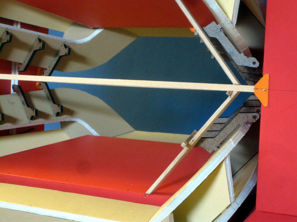
| (5) This is one of the Y-frames in the back. It is flush with the iron top and bottom. I have not cut away the central part of the horizontal bar, to be done later.
|
|
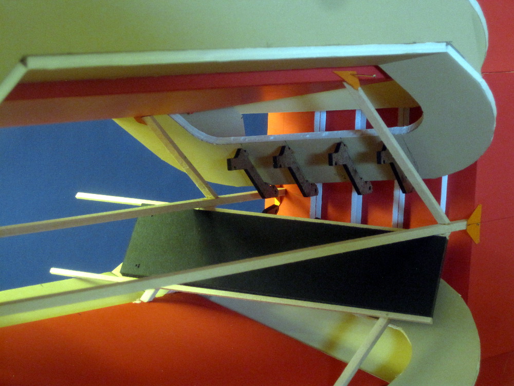
| (6) The detector plane is parallel to the plane of the coil, and just clears the coil support brackets. |
|
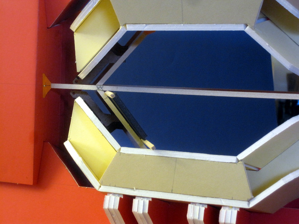
| (7) In this picture, I have placed a 1x4m box between the rails. |
|
| (8) Y-frames on the target side. The central part of the horizontal bar has not been cut out yet. |
|
| (9) |
|
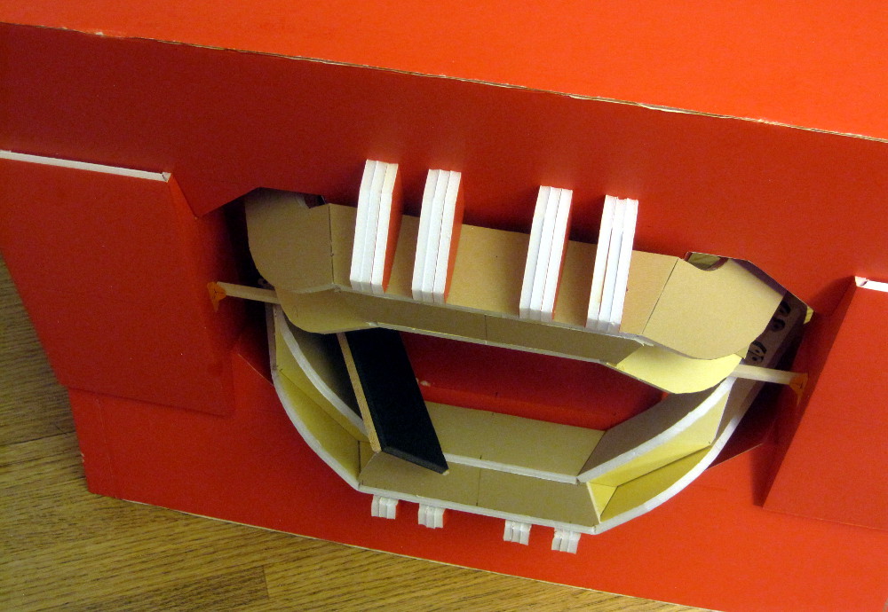
| (10) Here you can see how the panel slides out in the upstream direction. Clearly this will interfere with the upstream detectors... |
|
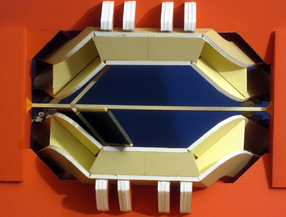
| (11) The bottom rail of a 1m detector box clears the magnet coil. (next I'll add the beam pipe support cables, to see if there is any interference). |
|
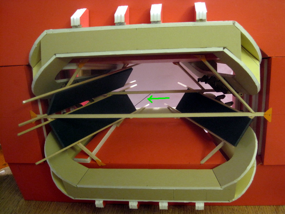
| (12) Three chambers installed. The green arow points to one arm of the spider that holds the beam pipe near the front. The spider wires in the horizontal and vertical planes do not interfere. There are also diagonal wires going from the forward beam pipe attachment ring, and are anchored further towards the back. These are also cleared.
|
|
| (13) In the CAD image below I highlighted one edge block, an extender arm which protrudes from the magnet face, and the wire going to the beam pipe.
In the model on the right you can see that this wire interferes with the chamber. If the chamber were narrower (~80cm instead of 1m), it would clear this wire. Another option is to move the anchor points of the front diagonal wires a little closer to the center plane, so they clear the bottom of the chambers. |
|
| (14) The image in the previous panel shows that the bottom rails just clear the magnet coil. There also is a lot of equipment in the target area (what? where?) so that we likely cannot slide the panels in straight. Instead, a rail system needs to allow for a path that curves away from the center plane. We need a description of the equipment that will be in this area at the time of installation. Note that a simple curved path such that the top and bottom rails have the same shape and length is not possible, since this would conflict with the magnet coil. A rail system that moves the panels (or panel sections) along a horizontal path out of the magnet and off to the side needs to be designed. | 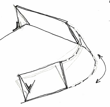
|
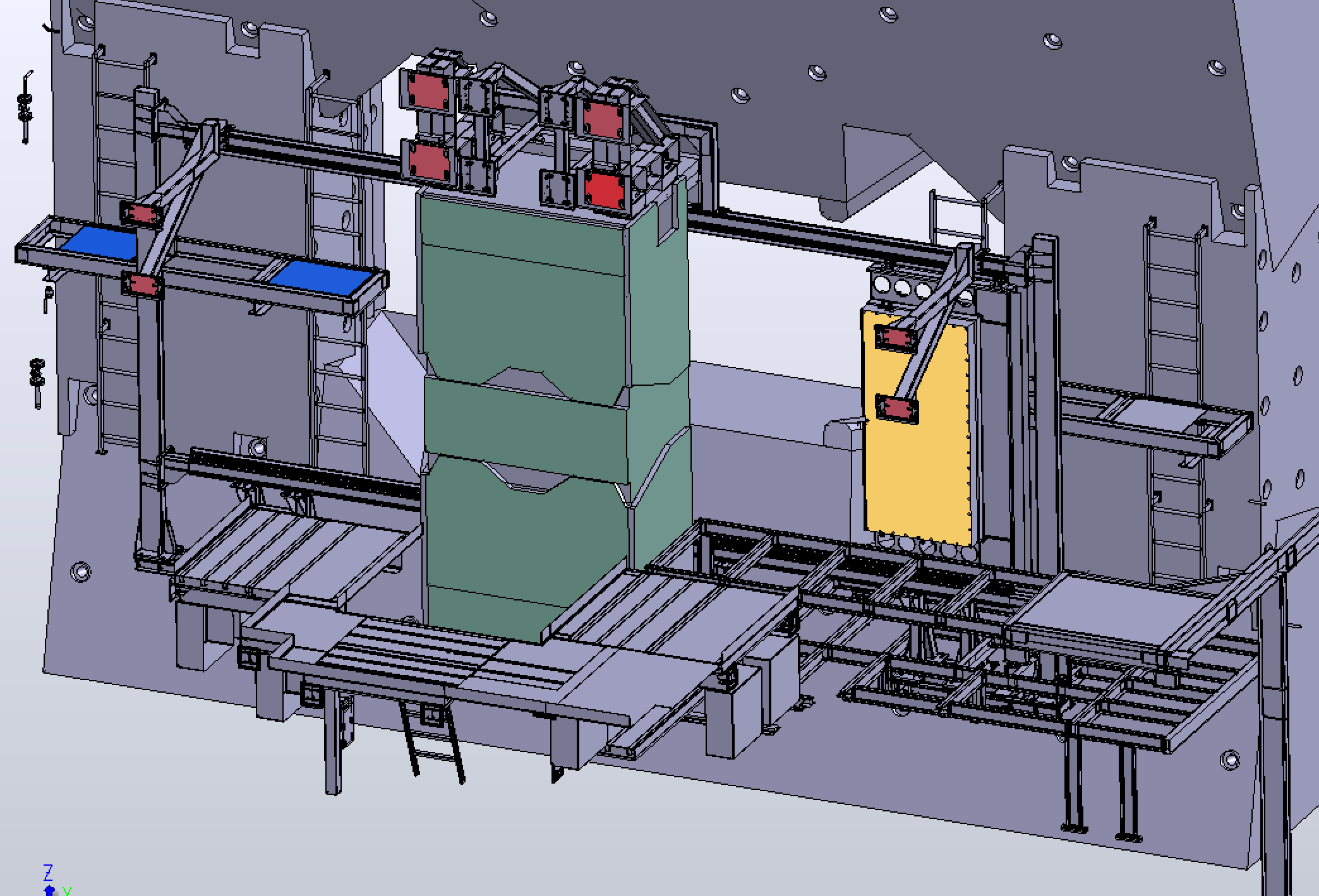
| (15) We got a new CAD file, showing the entire hall. A selection was converted to an EASM file. Upstream view
| 
|
| (16) View from downstream | 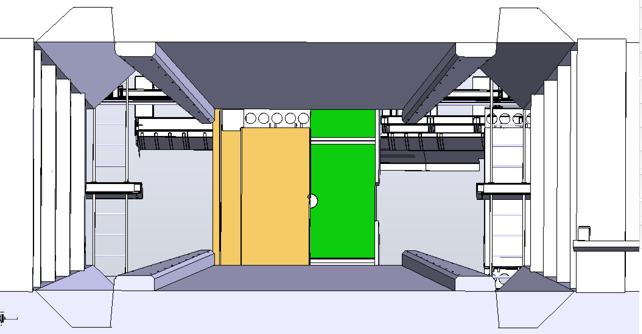 '
'
|

back Hubert van Hecke Last modified: Tue Apr 17 14:48:28 MDT 2018