|
I - Joining the boxes
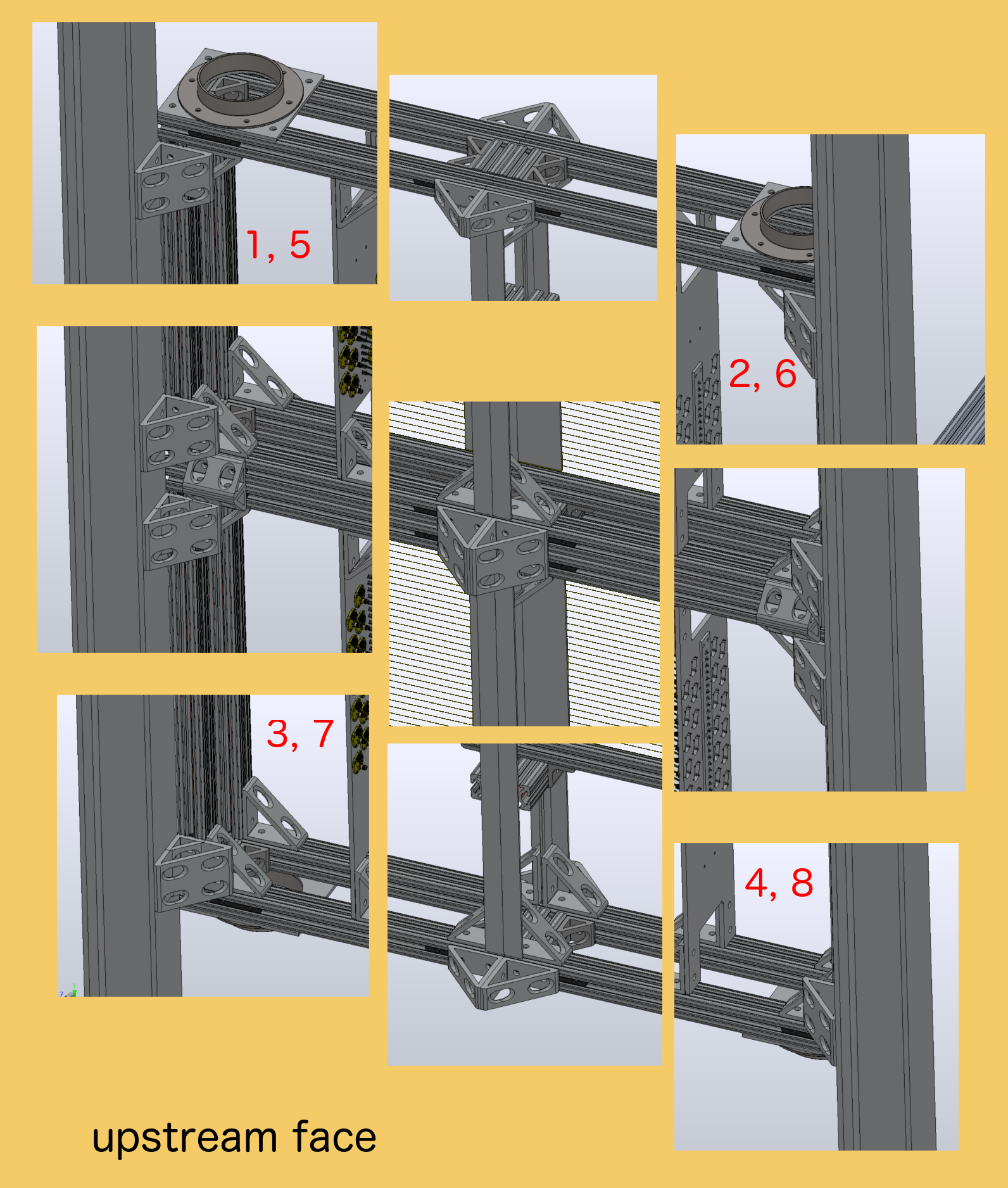
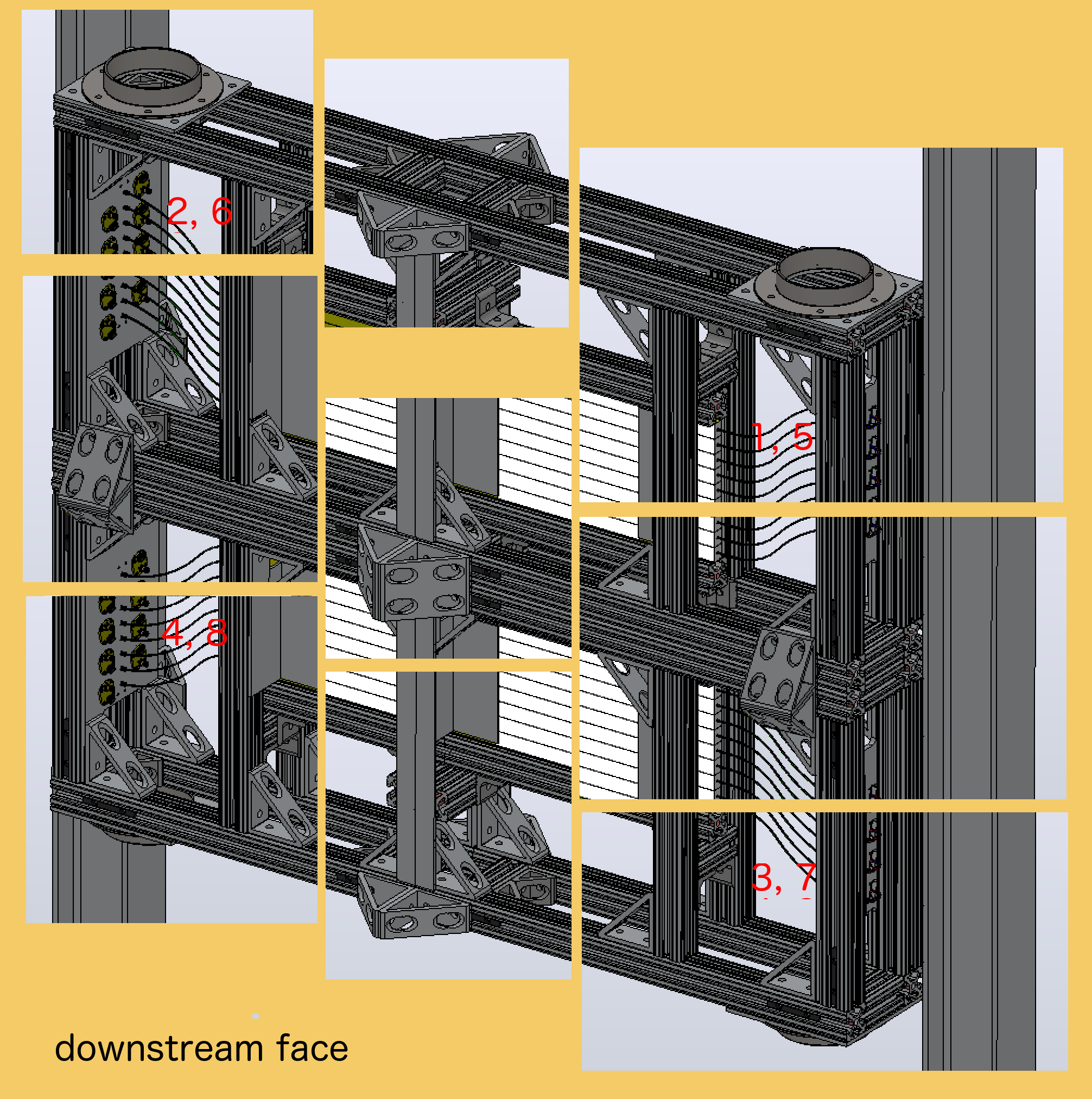
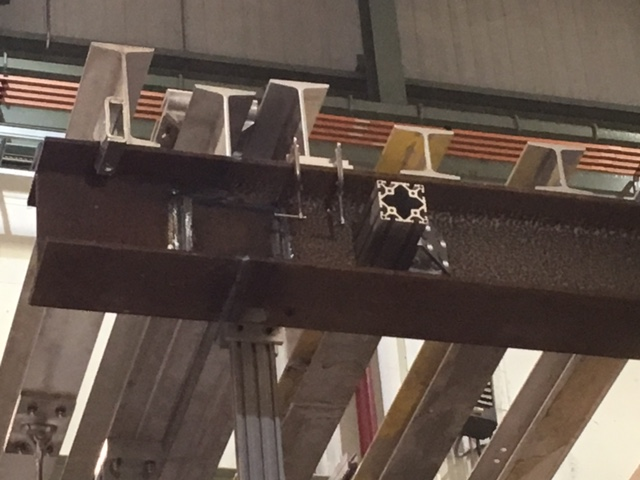
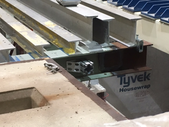
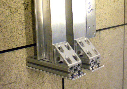
The top image shows the brackets used to join the boxes, and to mount to the posts. These are the joints of the 80-bar boxes (station 1), looking at the upstream face. The second image shows the brackets used to join the boxes, and to mount to the posts. These are the joints of the 50-bar boxes (station 2), looking at the downstream face. The assembly procedure to join the boxes is as follows:
Now join the boxes, and connect the vertical posts:
|
|
|
Raw measurements made in the hall
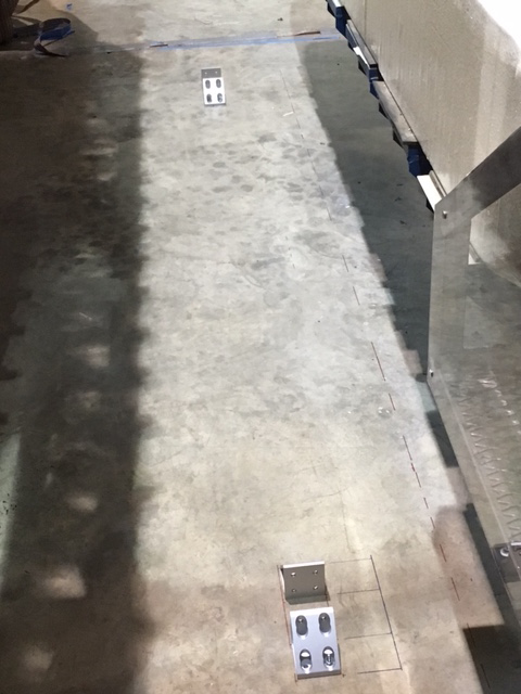
II - Station 2 location Station 2 is lifted by the top crossbar, and dropped down onto the steel of the A-frame, leaving a 3" gap to the box beam.
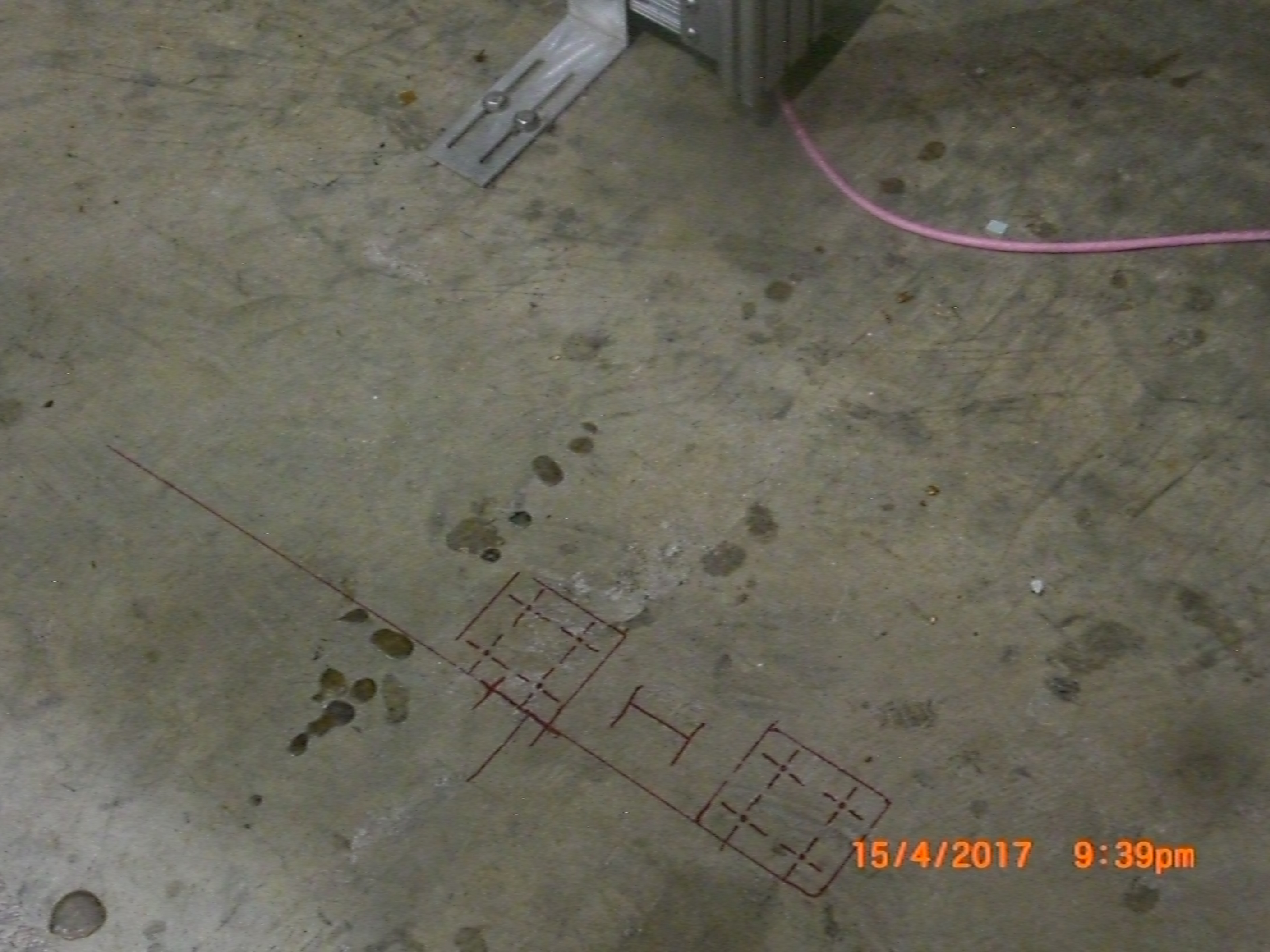
On the floor, the posts are anchored with a pair of brackets each. We have marked where the posts and anchors are located. | 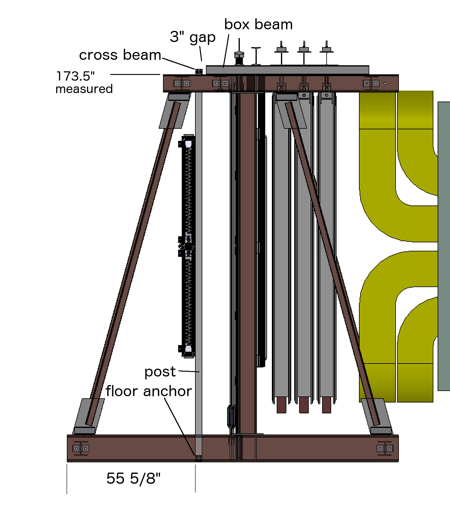
|
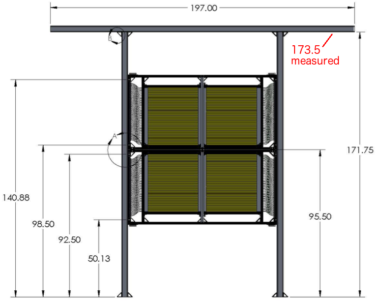
| The vertical beams are 171.75" (from the CAD drawing), as in this
drawing from the safety
document. However, we measured to the top of the I-beam (11 May '17) to
be 173.5", 1.75" higher.
To fix that, we mounted a foot tothe bottom of the posts, consisting of
1.5" 80/20, plus 1/8" shim plates.
|
|
|
III - Station 1
The measurements in black are taken from E906spectrometer2-17.EASM. The measurements in green are taken in the experimental hall. There are a number of significant differences. In red is the position of the detector. Note there is some almost-interference at the top with the box that covers the magnet power leads. However it clears the detector corner in the x-direction by 3.125", and I moved the detector out so that the upper coax cables remain easy to service. The top of our posts is 3.25" below where they should be if we want to bolt to the center of the 8" I-beam. More on that below. | 
|
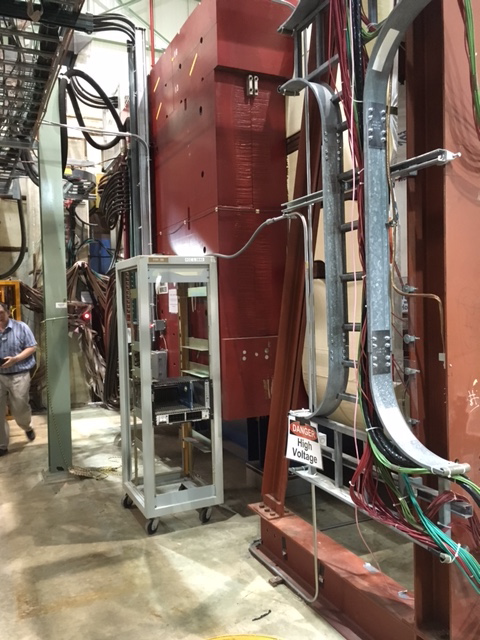
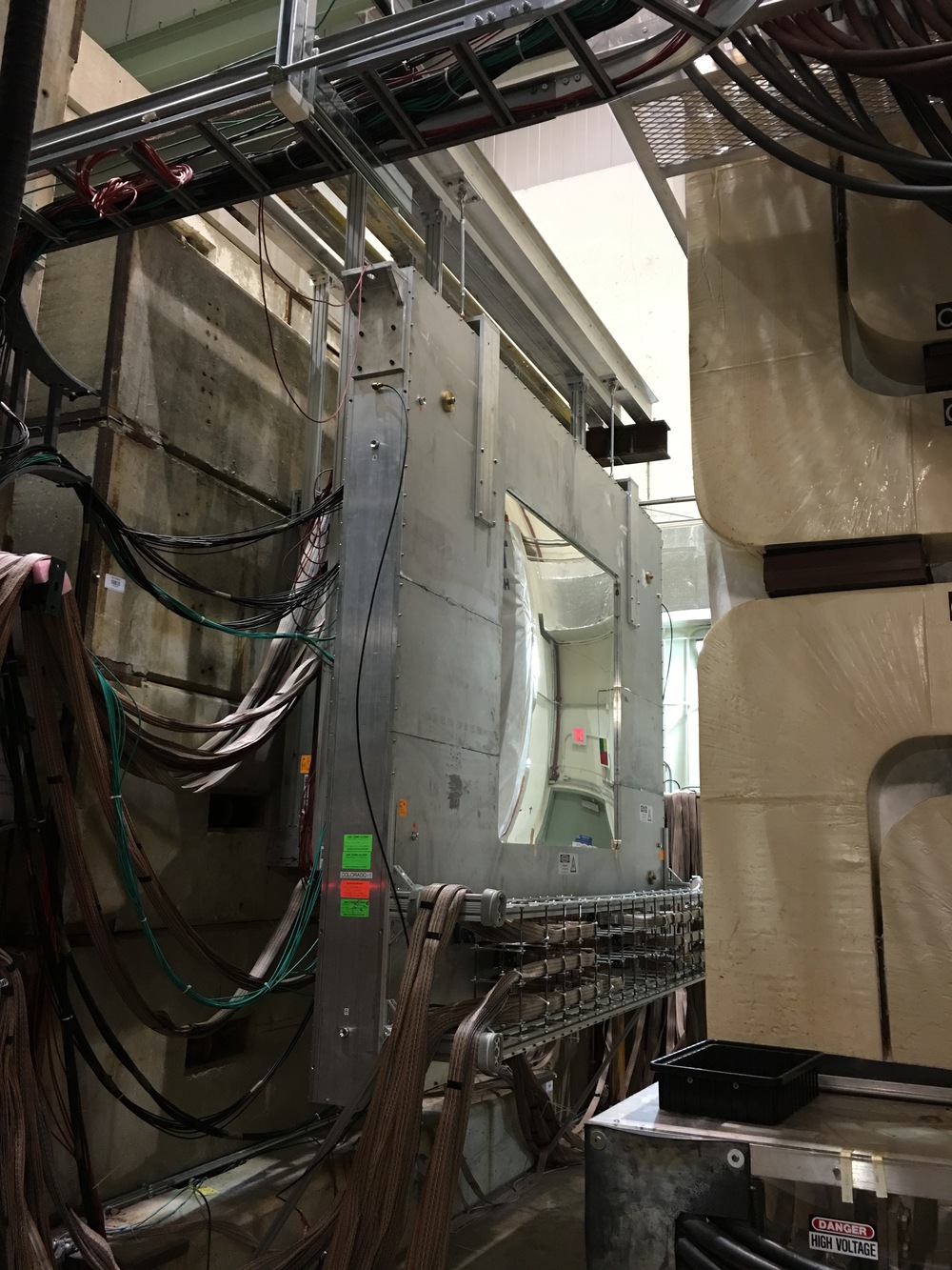
| For the extenders, we need to leave enough transverse space to lift the station-1 drift chamber out. This chamber would be raised a hair, then moved downstream until it clears the big I-beams, and then lifted up and out. This means our extenders need to be mounted out a bit to provide enough clearance width. See this picture - the drift chamber is the Al box, 10'8" wide. Near the top, just visible behind this black hose, is a bracket that sticks out 5.25", on both sides. Plus a little over 3" on both sides for slack, gives a clear space of 145" between our extenders. In this sketch, I just draw flat pieces, but this could be C- or I-beams, or 80/20. We have to provide these, they will drill bolt holes in the I-beams (behind the weld of the current I-beam extension). | 
|
| The actual extenders are made of 3×3" 80/20. The bracket that
mounts to the steel I-beam has 4 holes for 5/16 bolts. There are various
options for attaching the extender arms to the I-beam, more on that below.
The installation procedure is:
| 
|
| Mounting the extenders to the beam:
First, we have to come down by 3.25" from the calculated position. By changing the way the short piece connects to the extender arm, we gain 3" - close enough. → There are 3 ways to attach this extender assembly to the big I-beam
| 
|
| This is a view upstream towards the st1 wire chamber and the I-beams, in grey. In red is indicated where the I-beams really are (the inside of the beams lines up with the edge of the chamber, as indicated. The chamber was measured at 128.5, the beam is 6.5" wide with a 1/4" web, so the extender spacing should be 135.25". Our mounting frame is made for 134.5" - close enough. | 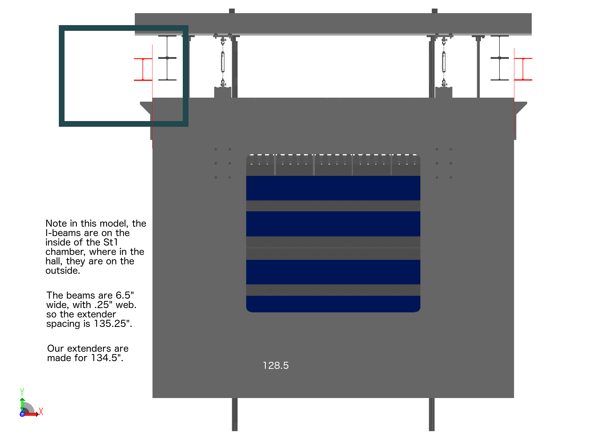
|
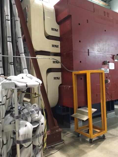
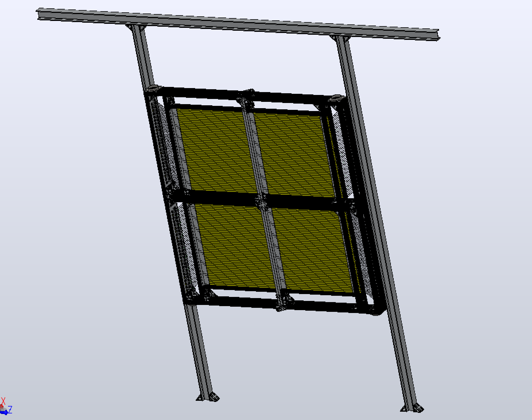
| (5) Cable trays: We have a rack (red) to either side of each of our detectors. Shown here is a beam's eye view of the first station. We propose to have cable trays (orange) mounted to the top of our racks, and on the other end supported by some bracket coming off our vertical post. Cables and fibers (yellow) go down (3 bundles) or up (1 bundle) to the cable tray. | 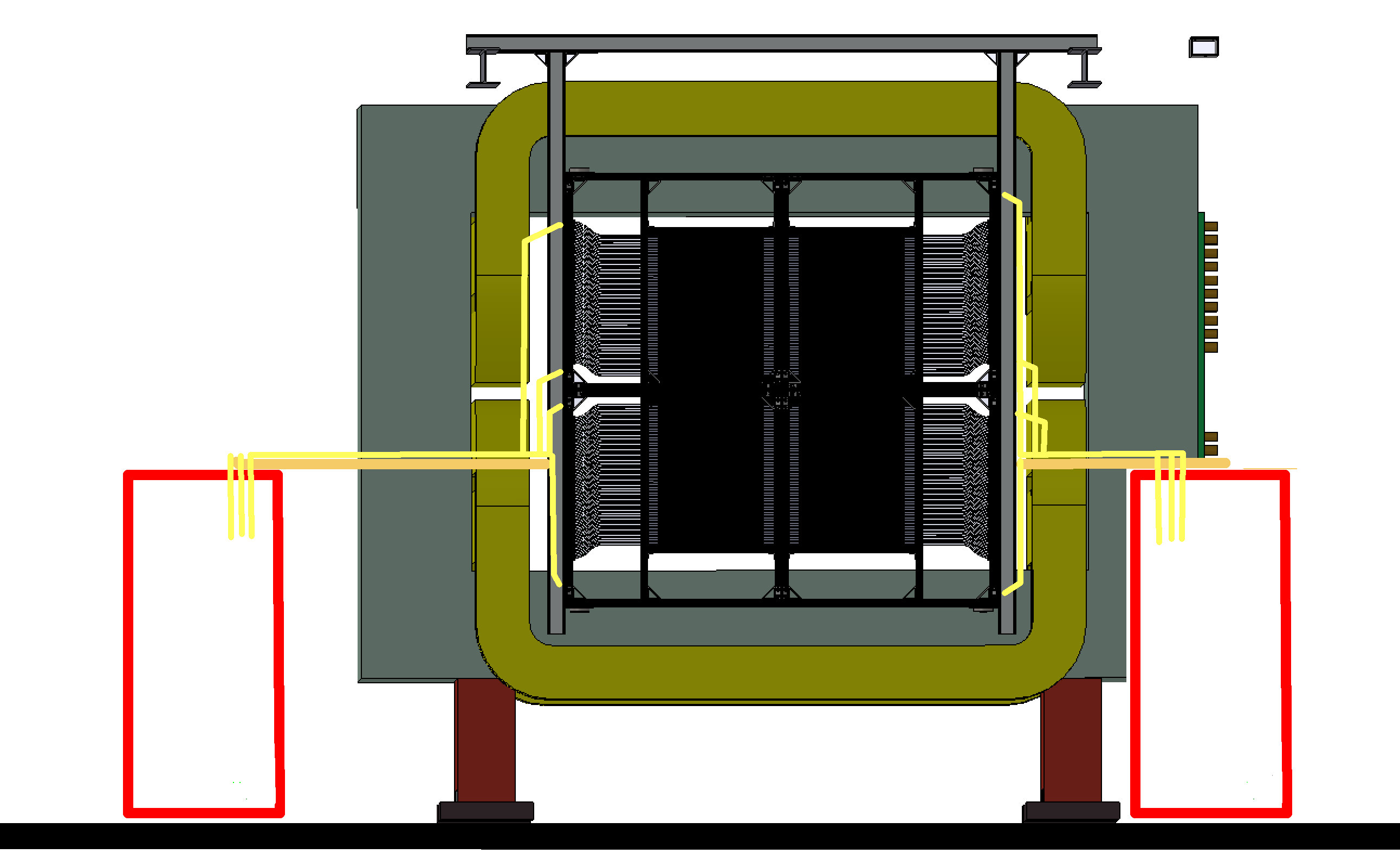
|
Brackets mounted, and racks placed (25 Apr 2017):
| |
Hubert van Hecke Last modified: Fri May 12 08:57:37 CDT 2017