| The calibration system uses an existing pulse generator (from Pat). Output fibers go to splitters, and from there 1mm clear fibers go into the scintillator bars | 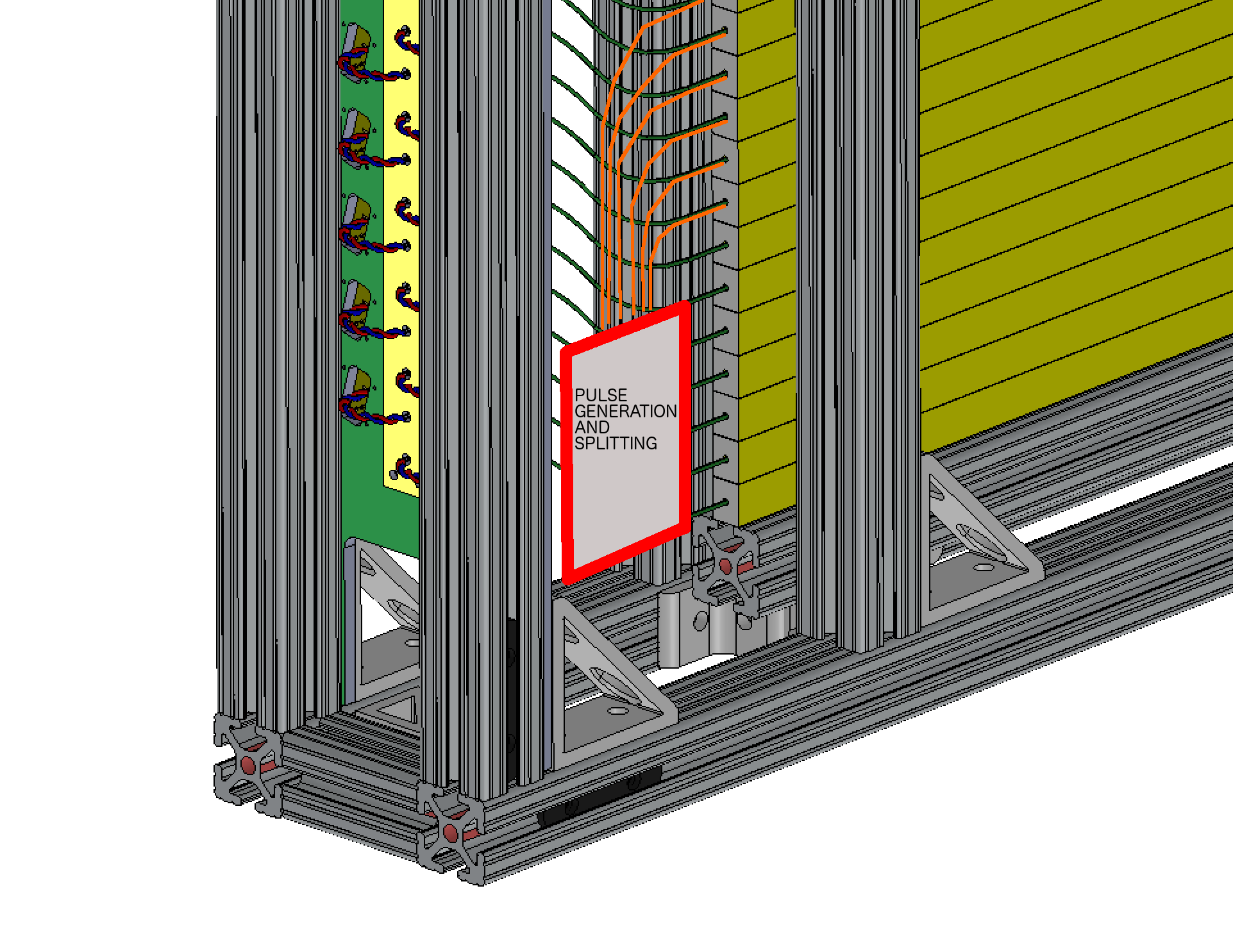
|
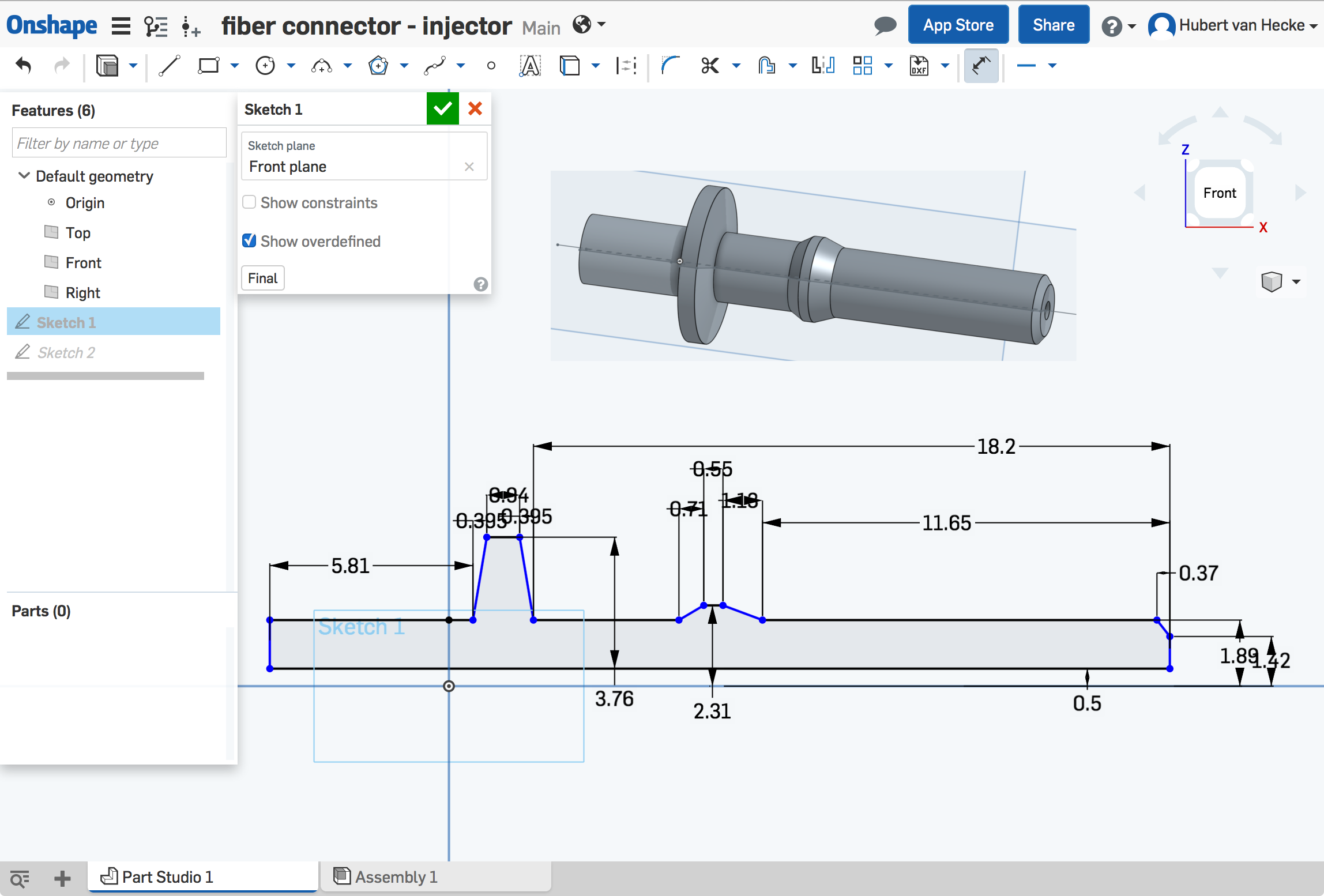
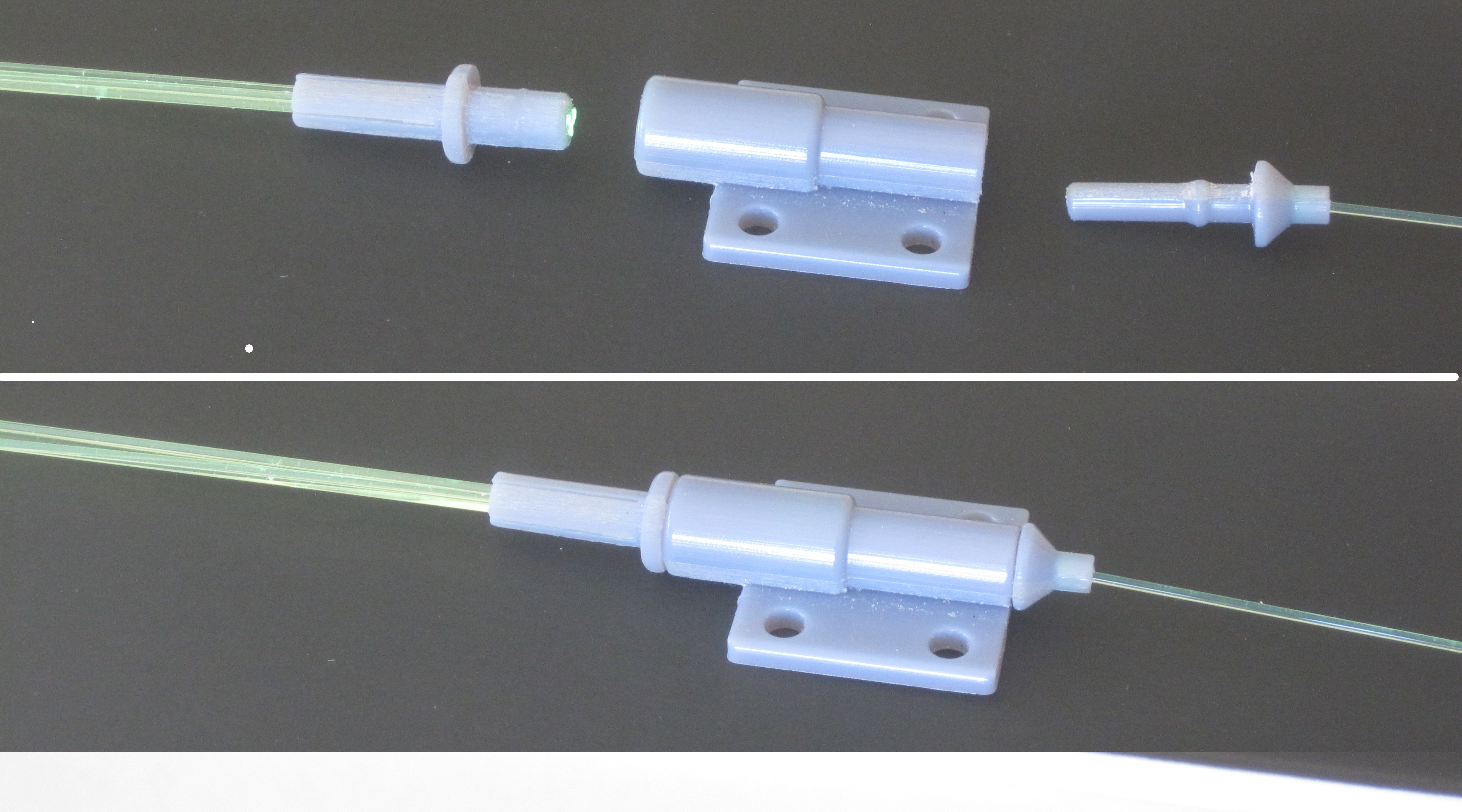
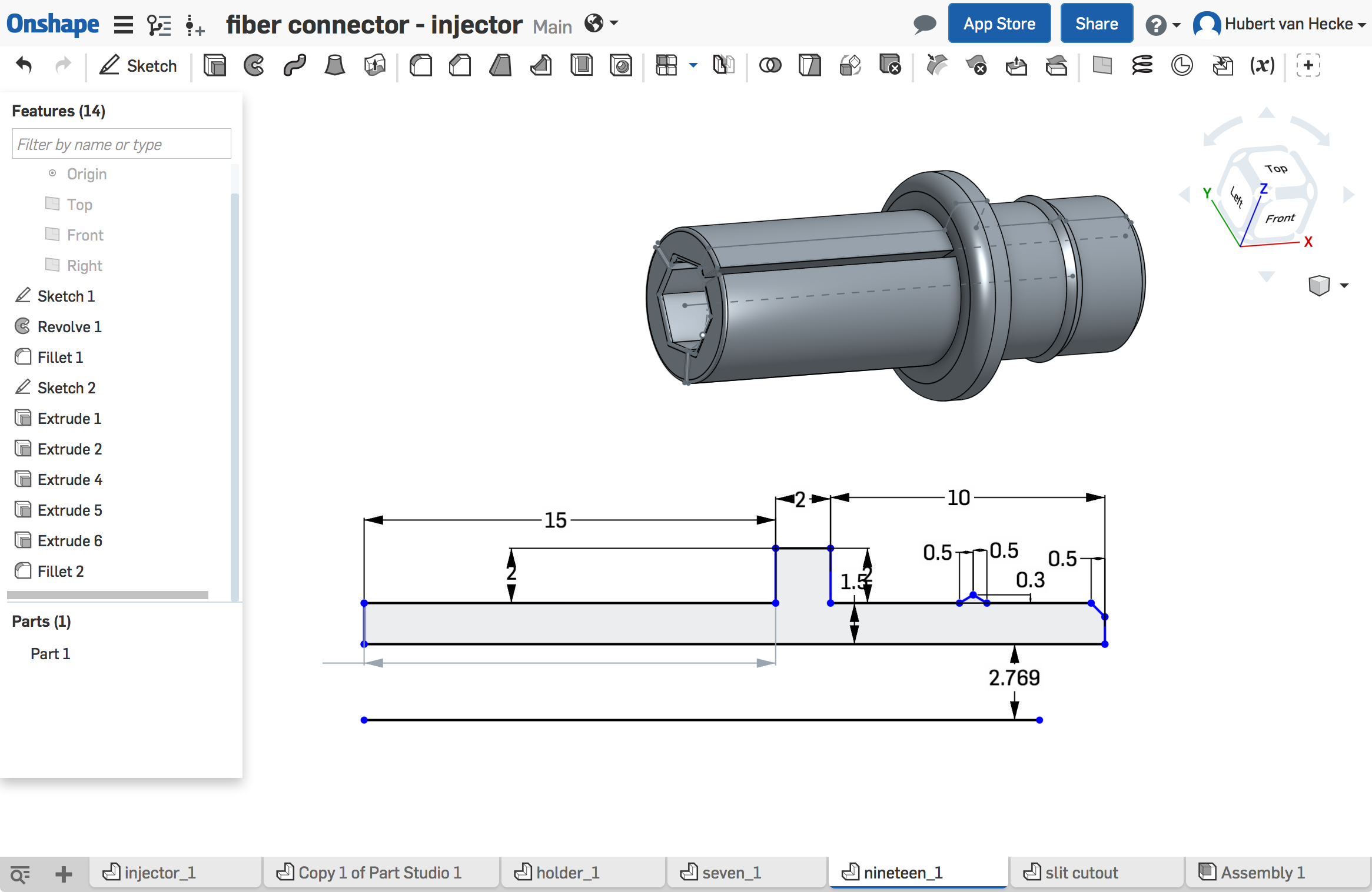
| Pat's fiber light injector ( Broadcom HFBR series), at digikey Measured up and entered into OnShape for 3D printing. 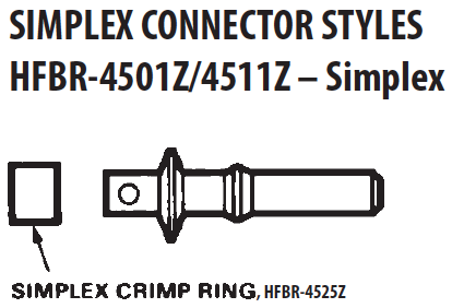
|
|
The injection fiber holder (above) clicks into the right. a piece that holds 7 output fibers snaps into the left. | 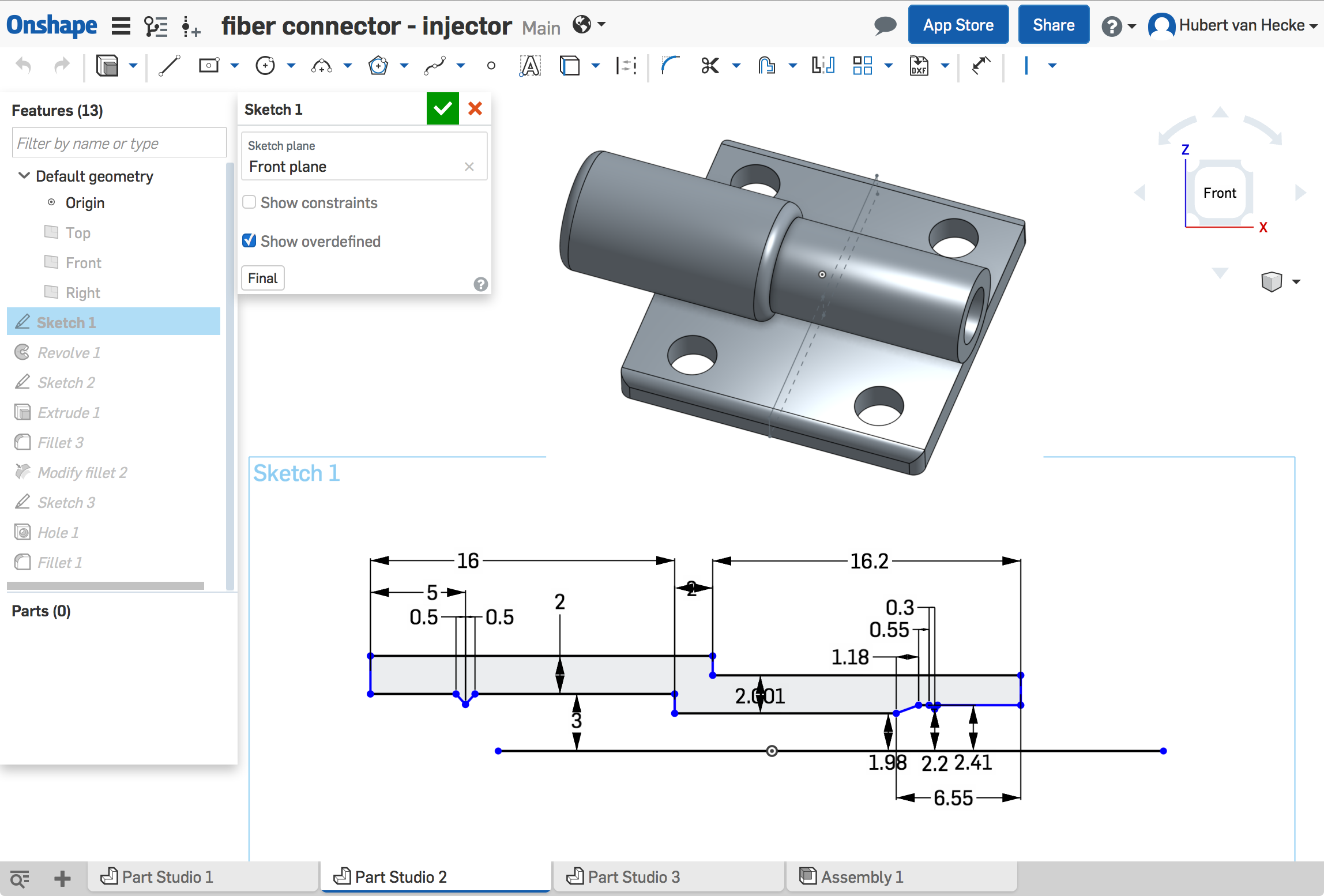
|
This holds 7 1mm fibers. The left half is split so it can be squeezed to hold the fibers. The blue plate is a temporary foot to prevent tipping during the printing. | 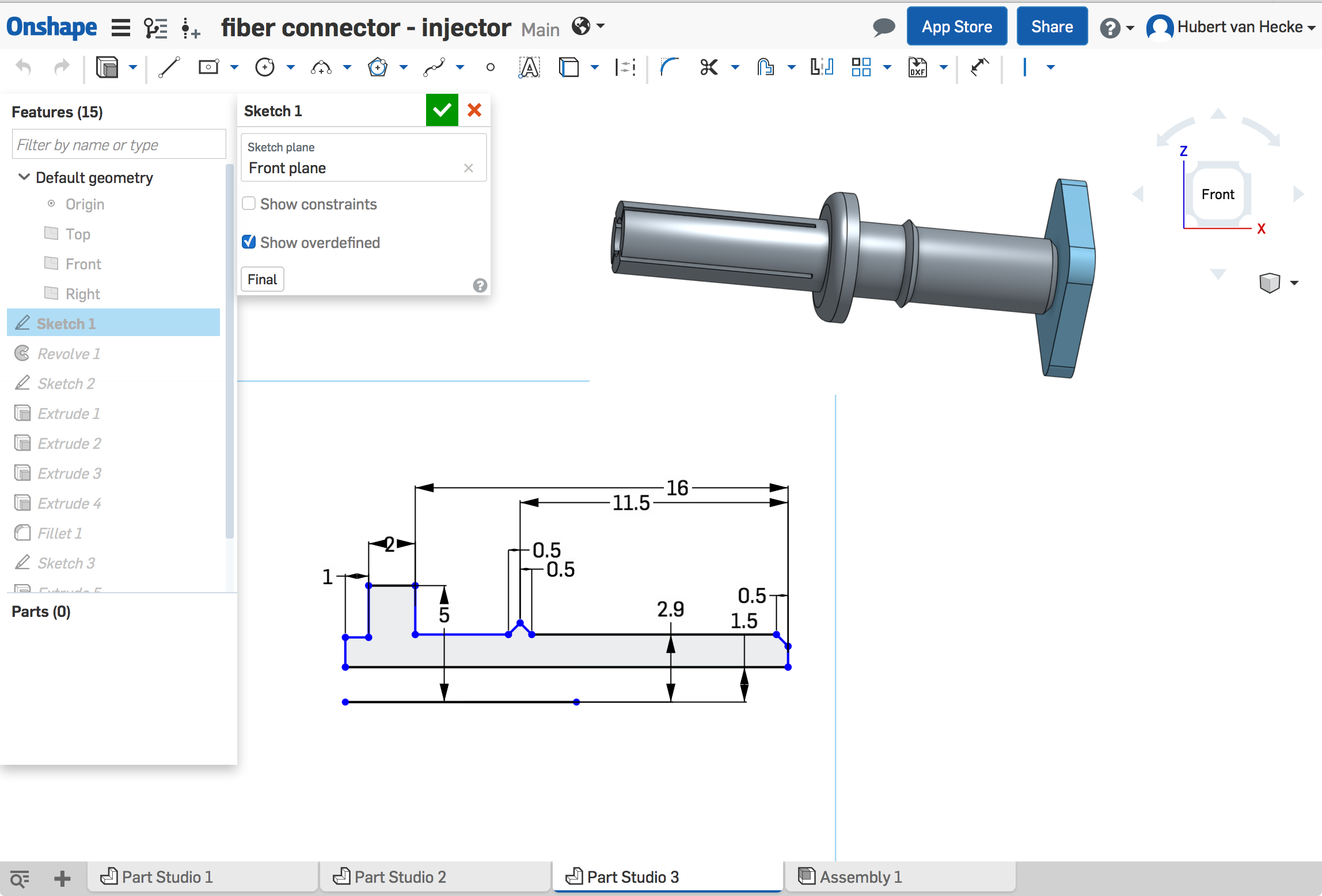
|
The three part should fit together - let's print them and see. | 
|
| Splitters are 3D-printed. Shown is the first prototype of a 1-to-7 splitter. Through holes are a little too tight. Reprinted. |
|
| Holder for 19 fibers (1+6+12 makes a hexagon). The through-hole is now hexagonal, and the splits are in between 2 fibers. |
|
| Fiber holders printed for 7, 19 and 37 fibers. The bright fibers
(2,3 and 4 respectively) are long fibers with polished ends. The
others are short pieces with razor-cut ends.
They fibers fit snugly, and by wrapping the split back with thread and wood glue the fibers are locked in place. However, for the 37-fiber holder, this is not sufficient to prevent the fibers in the center to be moved. Therefore we will use the 19-fiber fanouts. | |
| onShape | |
| Three small plates hold the calibration fiber fanout bits. The ones at the top (green) service the bottom half, and vice versa.
Maximum length of the calibration fibers for the 1m units: 180cm or 71".
We will have headers at the back plate, rather than have the input fibers hanging out. For the 50-bar unit, we need three 1→19 splitters. The bottom one (red) services the top 1/3, and the top 2 (green) service the bottom 2/3. | 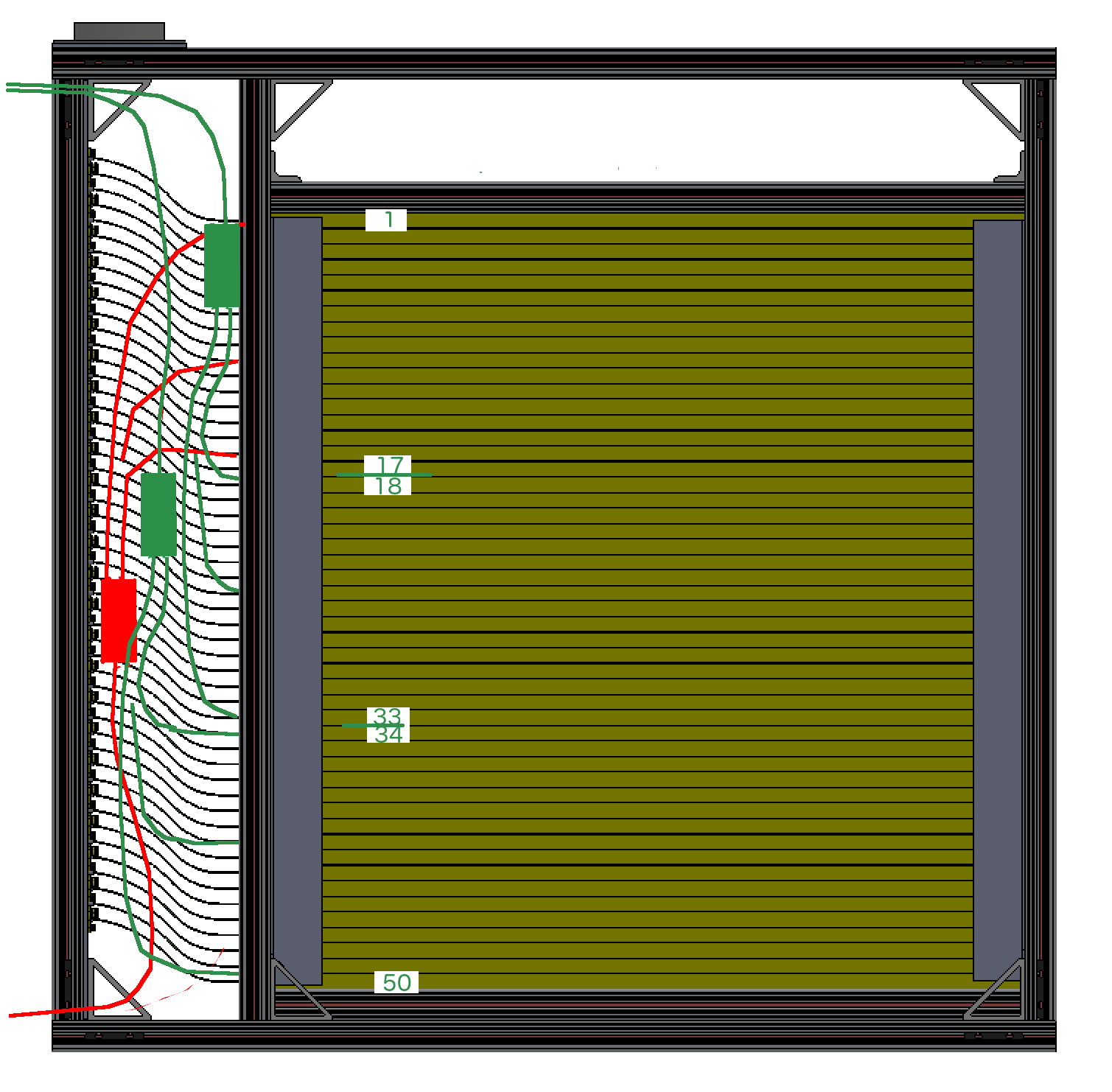
|
| For the 80-bar unit, we need five 1→19 splitters. The bottom two (red) service the top 2/5, and the top 3 (green) service the bottom 3/5. So we need a total of 32 1→19 fanouts. | 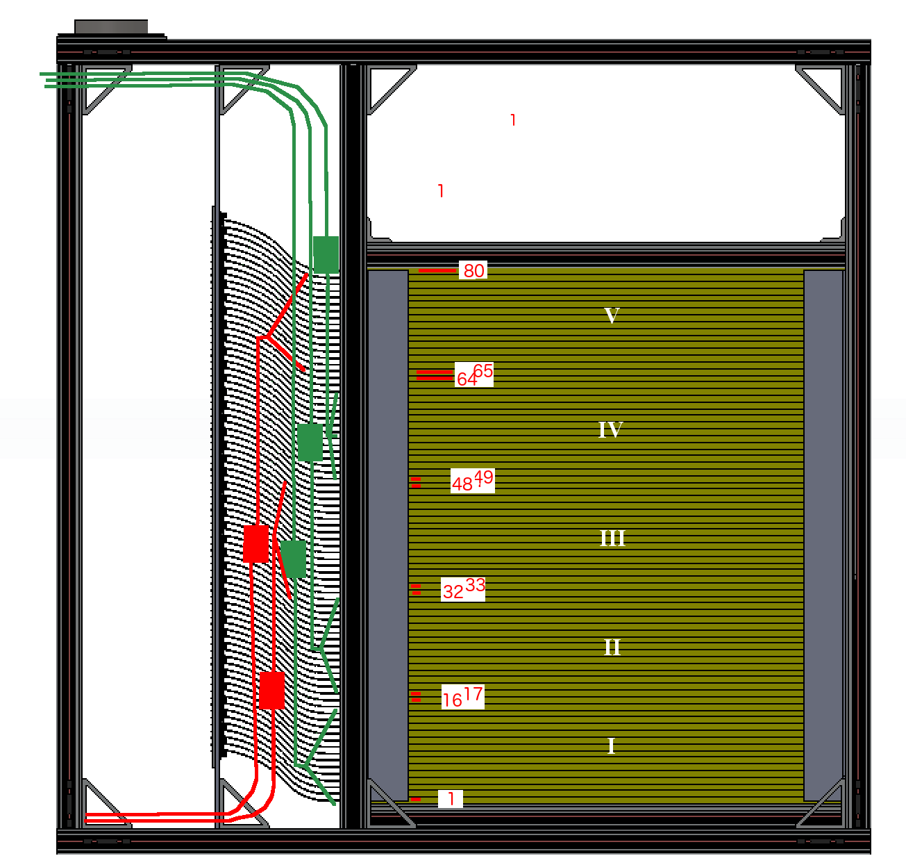
|
Hubert van Hecke Last modified: Thu Feb 16 09:57:26 MST 2017
