build a proof-of-principle prototype
back
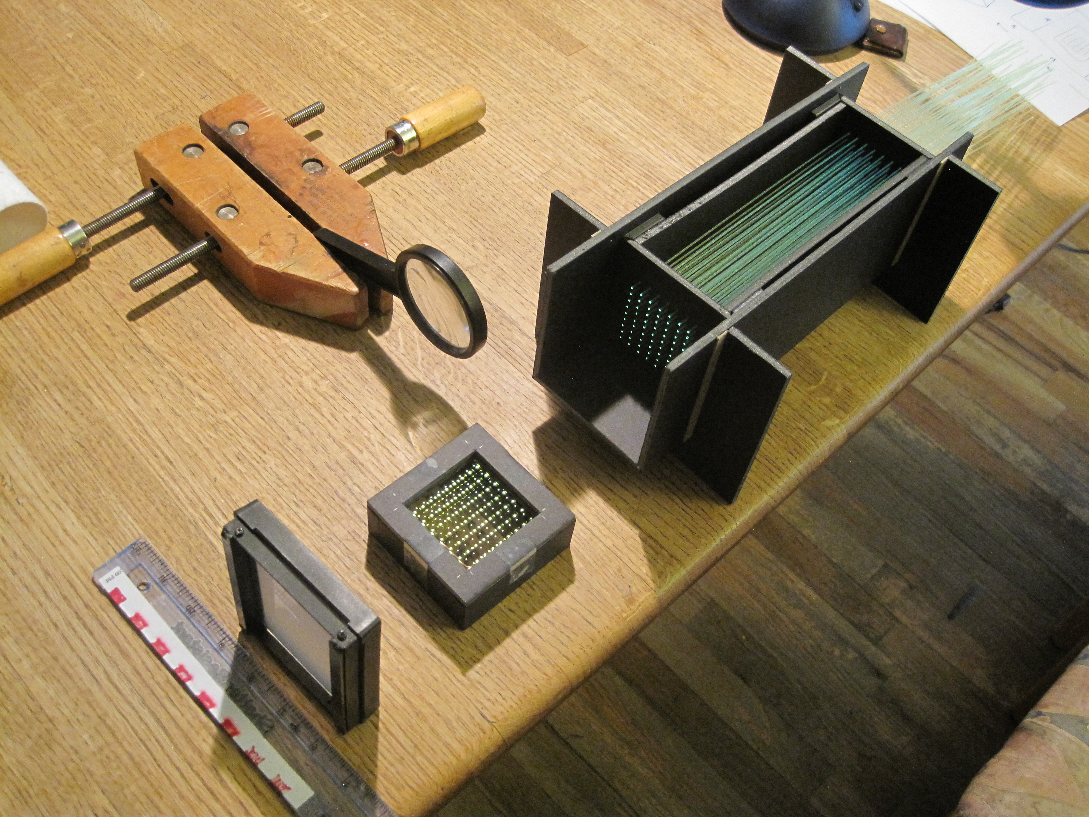
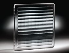
| I bought a
lens array from Edmunds. This is a rectangular
7×9 array of lenslets, 7×5.4 mm each. I built a matching fiber array,
using some 1mm plastic wavelength-shifting fibers I had. The other parts you can see are
a magnifying lens and a ground-glass screen.
Ambient light is enough to light up the fibers, but a small desklamp helps a lot. 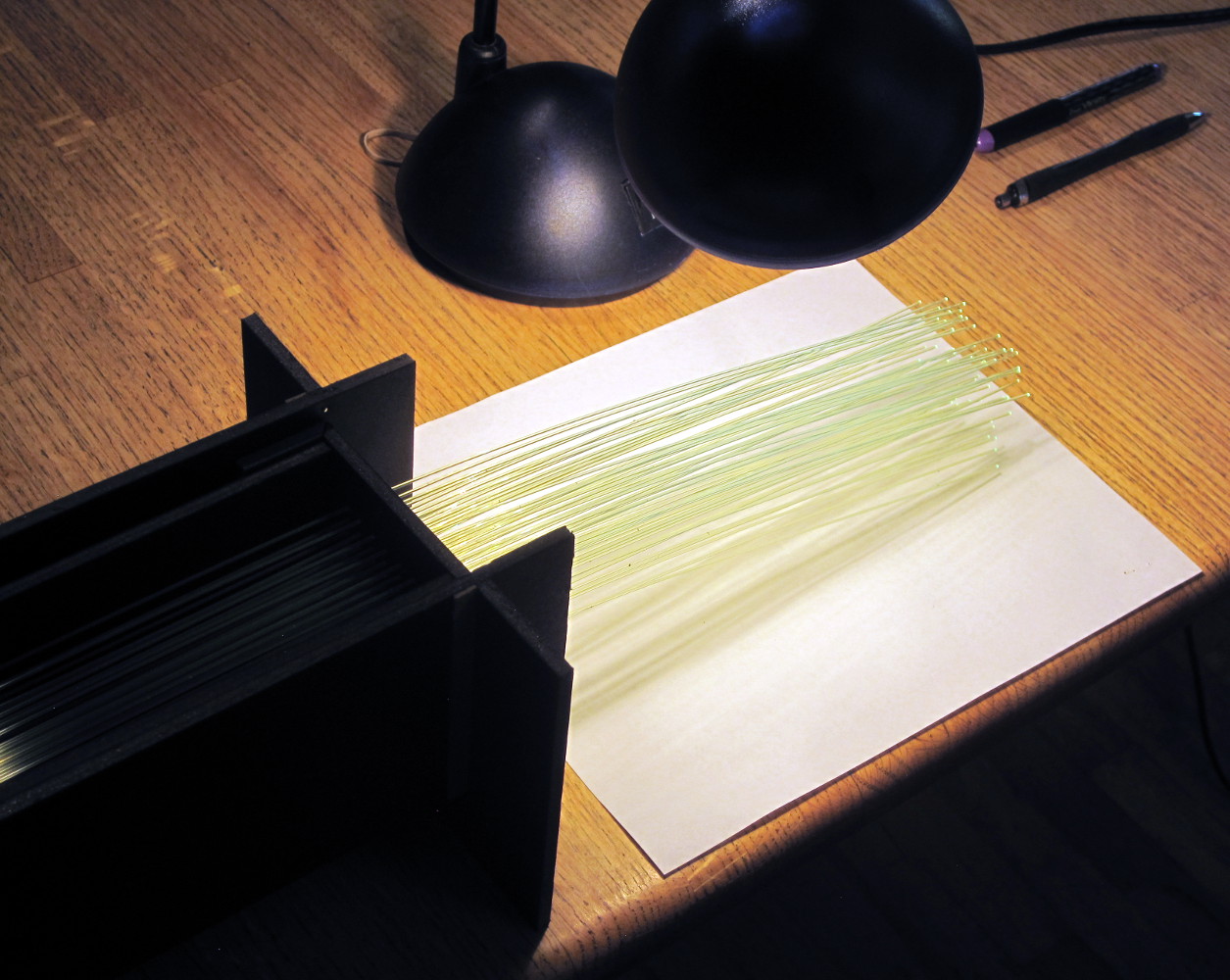
| 
|
| The fiber ends are cut with a razor blade, and are not polished. They appear to shine ~uniformly into 2pi. | 
|
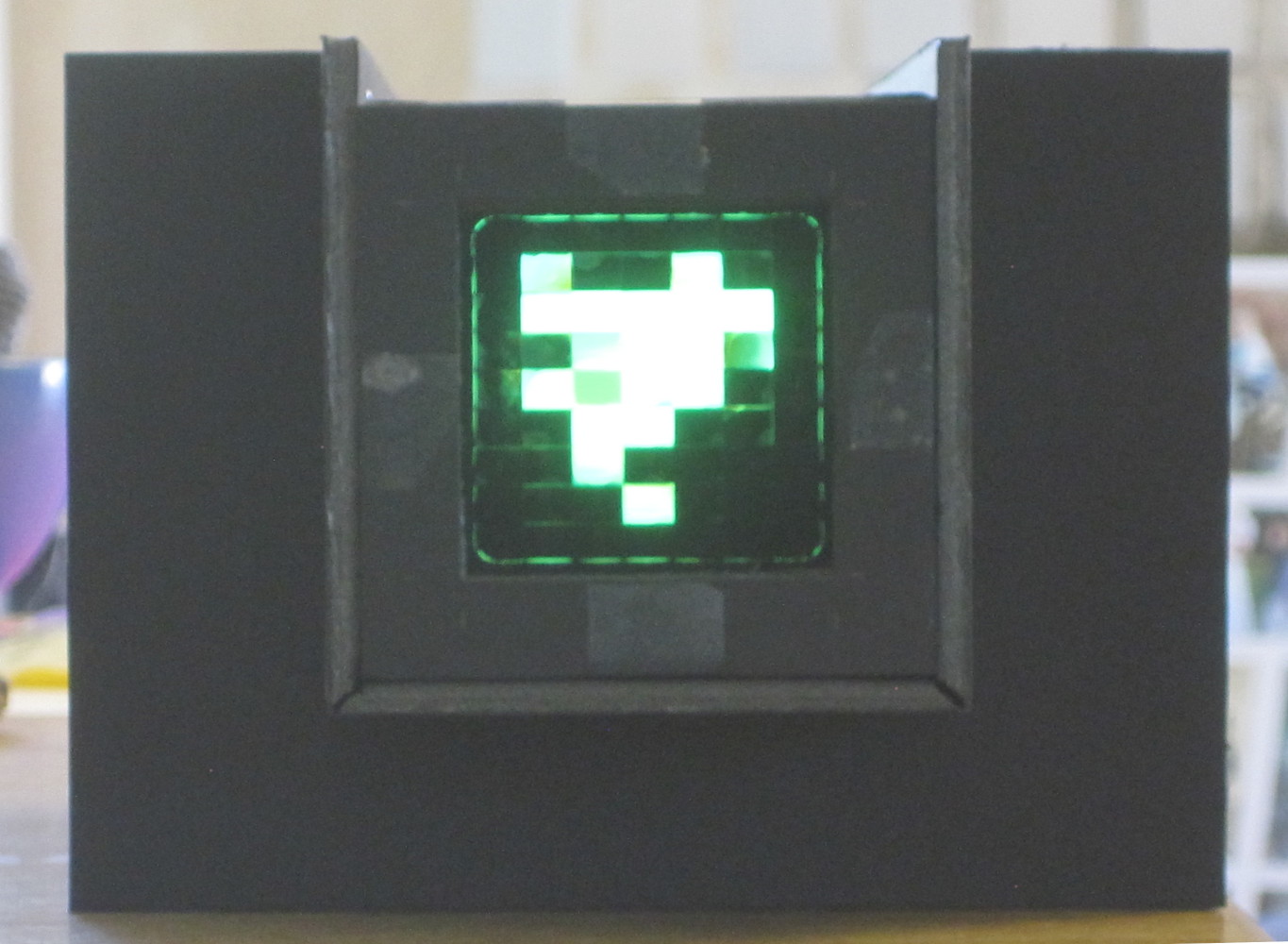
| When the lens array is placed in front such that the fiber ends are in
the focal plane of the lenslets, the light from the fiber which strikes its corresponding
lenslet will be sent parallel to the main axis, and fill up the lenslet if viewed from a
distance (here about 80 cm).
The lenslets in the perimeter appear dark, because the light from them travels parallel to the main optical axis at a distance of a few cm. The camera sits on the central optical axis, and does not see that light. If you move your eye to the bottom right, those lenslets will light up.
| 
|
| When the magnifying glass lens is placed in front, the light from
every fiber ends up in the central spot indicated by the arrow.
So what are those other spots? That is light from fibers in row, column (n,m) falling through a lenslet in row, column (n+i,m+j), i,j=±1, ±2.... | 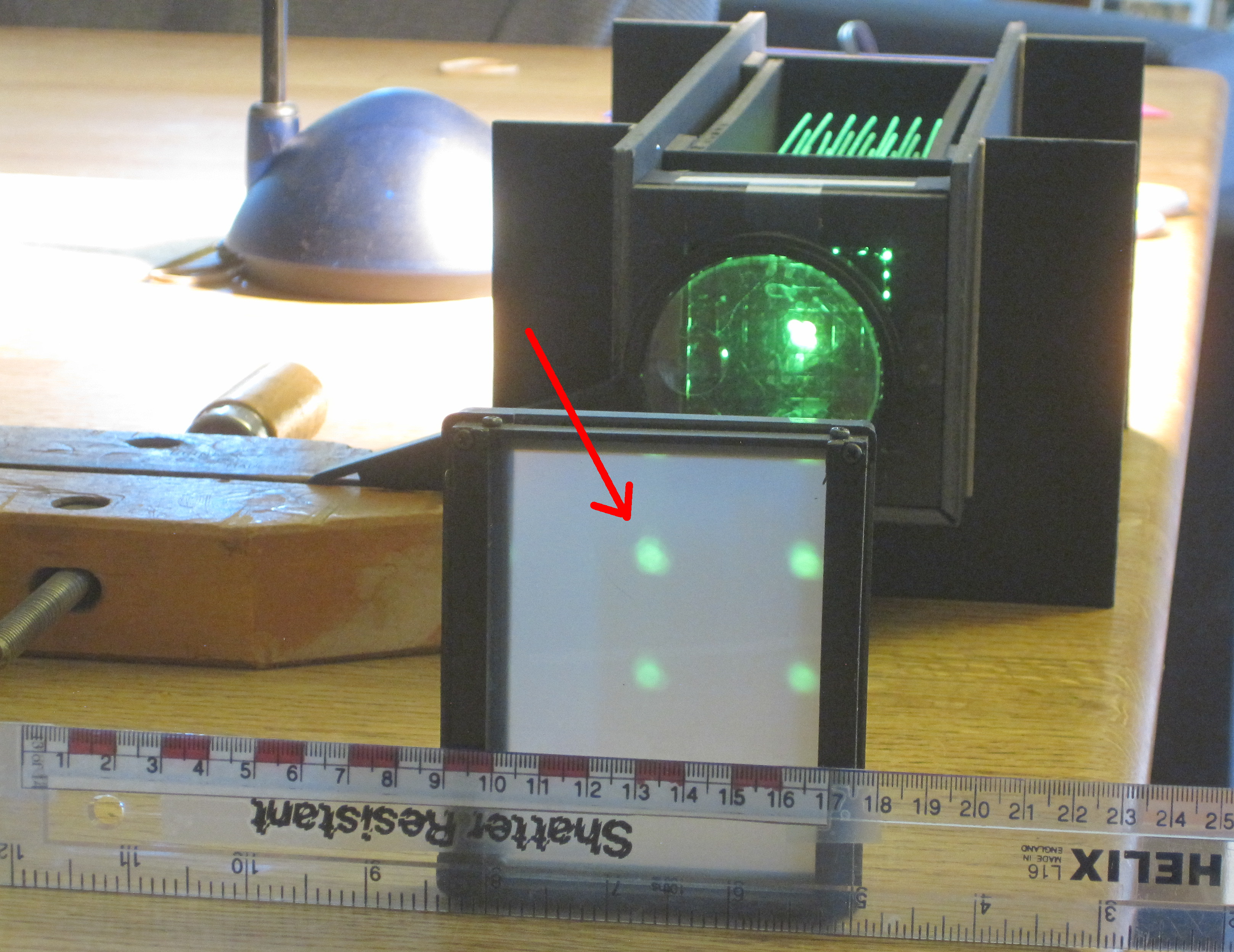
|
| The lens array is in the plane indicated by the arrow.
Here you can see that the focal length of the lenslets is very
long (42 mm) compared to the fiber spacing (7 and 5.4 mm). This leads directly to
1/r2 light loss, as well as those extra spots in the final
image plane.
You want the shortest focal length possible (among other things).
Making a lens array with VERY short focal length is hard. With a longer focal length, the 'multiple spots' effect will occur. If multiple SIPMs are required for other reasons (pixel count and dynamic range), we can exploit this by placing multiple SIPDs in multiple image spots. For a hexagonal array, the simplest arrangement would be a triangle of sensors. | 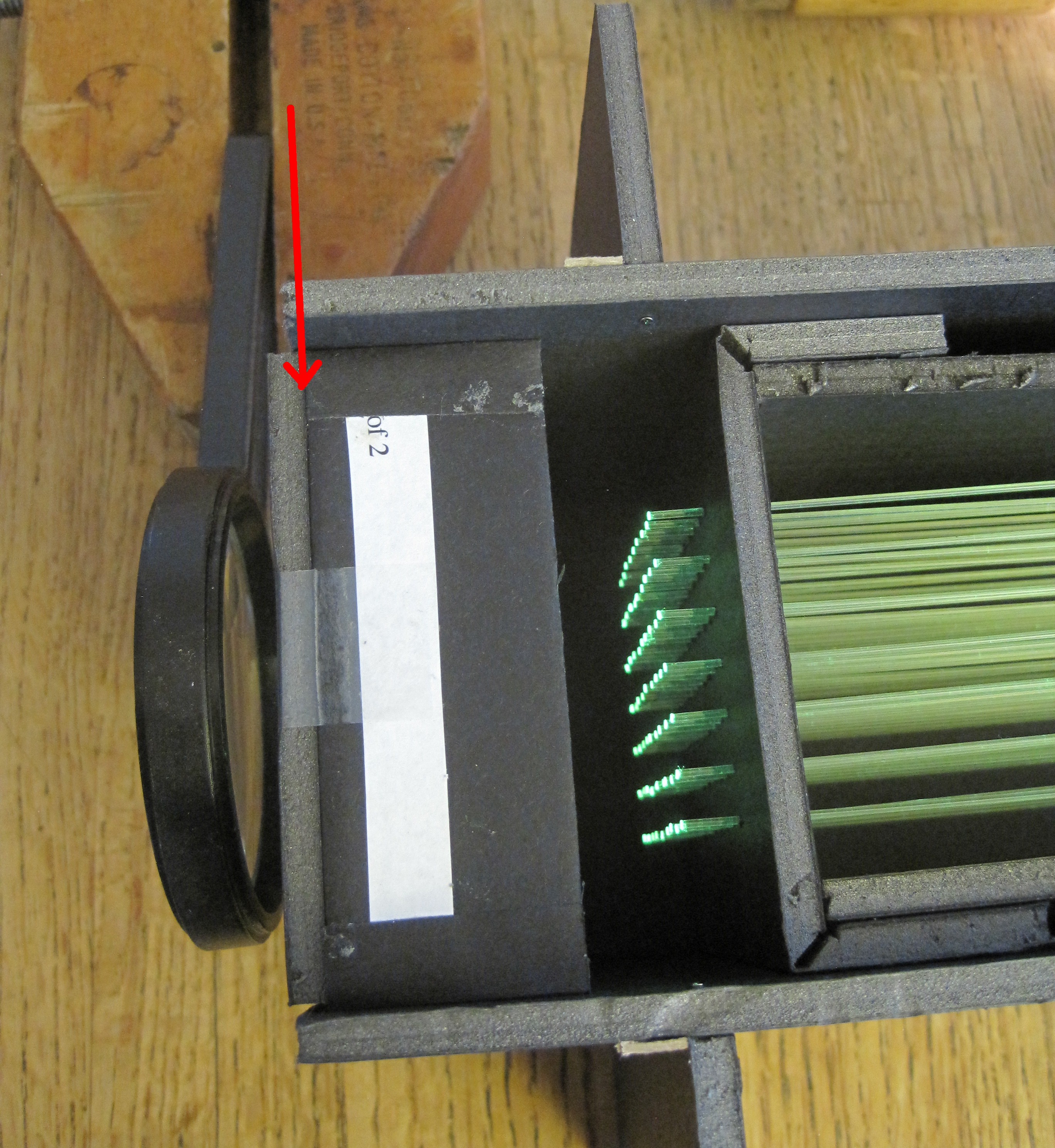
|
| Build a Geant4 model. Fibers, lenses, and a detector plane replicating the prototype. | 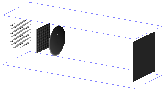
|
| Shoot photons, and you can see them landing on the screen. | 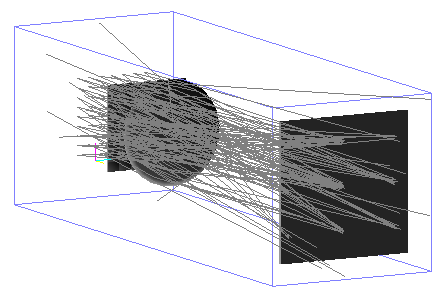
|
| You can see the images in the detector plane (scale is in mm). The space between spots is ~35 mm, same as in the photograph above. | 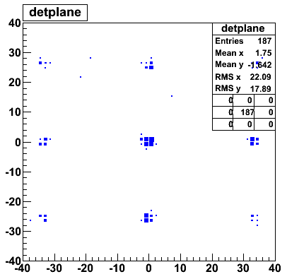
|
| Links and notes: | |
Hubert Van Hecke Last modified: Mon Aug 22 17:57:09 MDT 2016