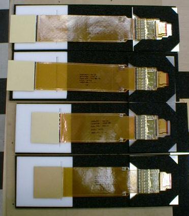
| Some assemblies of silicon, kapton cable, MCM and output cable. The silicon has a protective envelope over it. The top assembly is an 'inner top', the bottom ones are 'inner middles'. The MCMs are held by black foam glued to aluminum squares. | 
|
| Some assemblies after the kapton cables have been folded into the proper shape. The MCMs are upside down, under the aluminum squares. These are 'outer bottoms'. | 
|
| 'Inner bottom' assemblies, folded. | 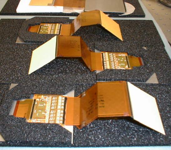
|
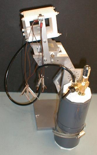
| An assembly fixture, set up for mounting of an outer bottom unit. Visible are an empty cage, and an empty plenum. The vacuum pickup fxture is on the outer bottom position. |
|
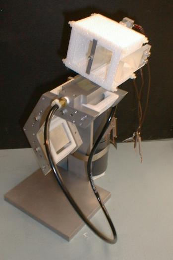
| Same unit, seen from the other side. |
|
| An inner bottom assembly, with the silicon on the bottom plate of the silicon pickup fixture. |

|
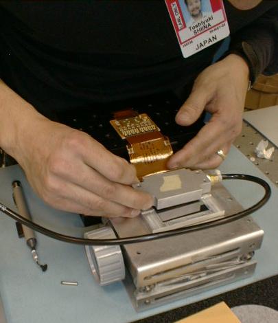
| The top part of the alignment and pickup fixture registers with the bottom part using alignment pins, and when vacuum is applied, the silicon can be picked up and transferred to the mounting fixture. |
|
| There are four mounting fixtures. These are oriented to receive inner bottom assemblies. |

|
| Ready for transfer |

|
| Applying epoxy (araldite) to the c-cage. The plenum is partially disassembled to receive the inner bottom MCM. |

|
| Assembly is transferred from the alignment jig to the
assembly fixture. The vacuum pickup block aligns with pins. Next the MCM is
seated in the plenum, and the rest of the plenum is put back together.
The whole unit goes into the environmental chamber for the 8-hour curing time. Four units pretty much fill up the chamber. |

|
| Several assemblies had unconnected bias lines. This could be fixed by soldering a very fine wire from the output cable to the kapton cable, bypassing the MCM and the wire bonds. A jig was built to hold the cage, disassemble the plenum and space out the MCMs so they could be worked on. |

|
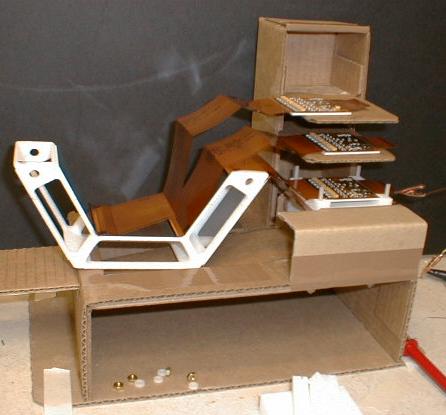
| The bottom half of the plenum is held tight while the top is disassembled and MCMs are place on removable platforms. The space underneath is needed for reaching the nuts on the bottom of the plenum. The removed plenum pieces are in the foreground. |
|
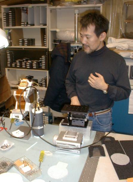
| Toshi mounting an inner top assembly |
|
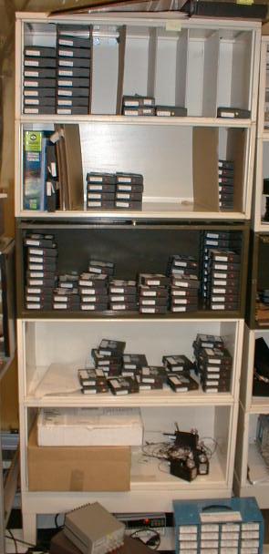
| All of the assemblies on these shelves are non-functional. |
|
| On some assemblies, there was a break in the bias-line connection in a place where it could not be fixed. In those situations, we connected a wire directly to the back of the silicon, using copper tape, backed up by a dot of silver epoxy. The copper tape turns out to make no contact with the silicon (presumably since the surface is so smooth - the tape's glue itself apparently does not conduct). A piece of the tape is folded under to provide the contact. |

|
| The copper tape tab is on the inner bottom silicon. The wire is led out of the cage via a groove cut in the rib, and follows the path of the kapton cables. |

|